 English
 中文简体
中文简体

Call us
+86-15105800222
+86-15105800333


On a 40 psi water line, a gauge mounted 7 feet below the pressure tap can read about 3 psi high before the system even starts. That error is enough to confuse pump control, mask a clogged filter, or make an operator adjust a valve in the wrong direction. A pressure gauge does not measure the pressure of the whole system. It measures the pressure at the exact point where its sensing element meets the process, plus any fluid head, friction, trapped air, or vibration that reaches that point.
Short answer: place the gauge where it can sense the pressure you actually need to control, on a stable tap, with a short and properly oriented connection, away from vibration, heat, pulsation, and dead pockets. It should be readable at eye level, isolatable for service, and protected by the right accessory for the fluid. If those goals conflict, the measurement point wins first, then safety and service access, and readability comes third.
This guide explains how to choose that location across water treatment, HVAC, steam, petrochemical, medical, marine, automotive, and food equipment. It also covers height, pipe orientation, isolation valves, siphons, snubbers, diaphragm seals, and the mistakes that create false readings.
The first question is not, "Where is there space for a gauge?" It is, "What pressure do I need to know?" A gauge on a pump discharge tells you the load on the pump. A gauge on a filter inlet tells you the pressure entering the filter. A gauge on a filter outlet, paired with the inlet gauge, tells you the pressure drop across the filter. Those three locations can show very different numbers on the same system.
For most industrial and commercial systems, the best location is a pressure tap on a straight run of pipe, at least five pipe diameters upstream and ten pipe diameters downstream from valves, elbows, reducers, and other fittings. This distance reduces turbulence and local velocity effects. The tap should be perpendicular to the pipe wall, not angled into the flow. A gauge connected to a long, narrow dead leg can respond slowly and can trap air or liquid that changes the reading.
Static pressure exists when there is no flow or when flow is temporarily stopped. Dynamic pressure is affected by velocity, friction, and pump behavior. If you want to check static pressure in a domestic water system, install the gauge near the main shutoff valve, on a branch that is not flowing. If you want to monitor pump discharge pressure, install it close to the pump outlet but after the check valve and before the first major restriction. If you want to see the pressure available at a fixture, install it at the fixture branch, not only at the main.
For control decisions, choose a point that reacts quickly enough for the control loop. A gauge placed far downstream from a pump can be slow to show a pressure change because the piping volume dampens the signal. A gauge placed directly on a pulsating pump outlet can wear out quickly unless it has a snubber, restrictor, or liquid-filled case.
Practical rule: If the gauge is used for a safety trip or an alarm, locate it where it sees the hazard first. If it is used for routine monitoring, locate it where it represents normal operating pressure without being disturbed by temporary flow changes.
Before finalizing the location, confirm the gauge range, accuracy, connection size, wetted materials, and case protection. A well-placed gauge with the wrong range or material will still fail. For a broader review of range, accuracy, connection, and accessory choices, see this guide to pressure gauge selection and use.
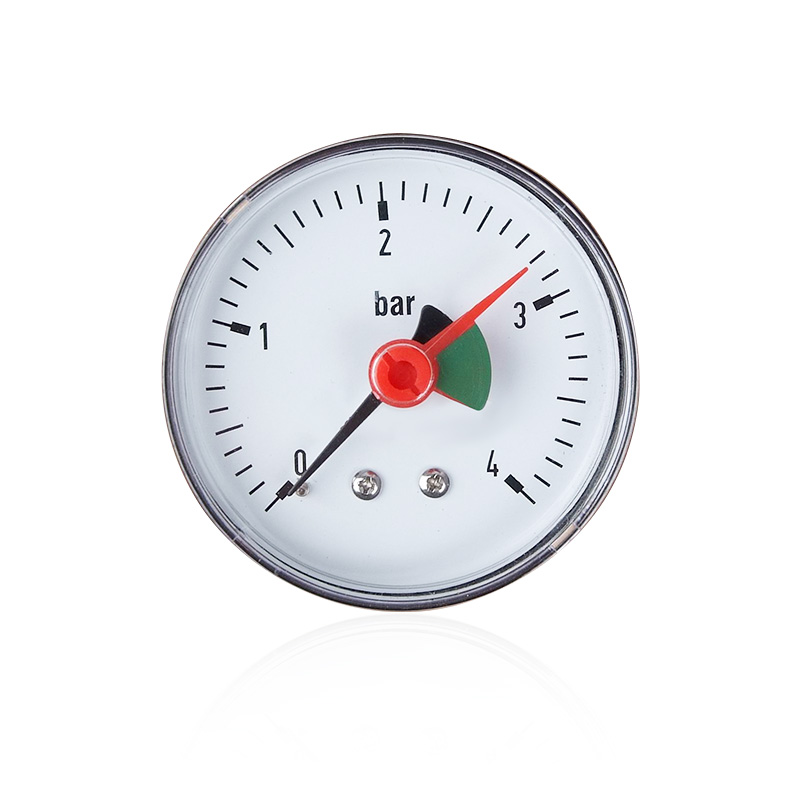 Y50 Pressure Gauge ManufacturersThe Y50 series pressure gauge uses high-quality pressure sensors and measuring elements with excellent accuracy and stability. The Y50 series can provide accurate pres...View Product →
After the measurement point is correct, set the height. For a standing operator, the center of the dial should sit between 1.5 m and 1.8 m above the floor or platform, roughly at eye level. For a seated operator, 1.1 m to 1.4 m is more comfortable. Small gauges with 40 mm, 50 mm, or 60 mm dials need to be closer to the eye than a 100 mm process gauge. If the gauge is above head height, a mirror, remote capillary, or pressure transmitter with a local display is often better than forcing the operator to look upward.
Avoid mounting a gauge below 0.6 m in areas with dust, washdown, or moving equipment. It may be kicked, sprayed, or buried under hoses. Avoid mounting it directly above a hot surface, open electrical terminal, or steam trap. The operator should be able to read the gauge without leaning over a guardrail, reaching across a rotating shaft, or standing in a traffic path.
Orientation matters as much as height. The dial face should be in a vertical plane for most gauges, and the connection should not be forced sideways. A gauge installed upside down or at an extreme angle can make the pointer hard to read and can affect liquid-filled gauges if the fill level is incorrect. If the pipe runs overhead, use a back-connection gauge or a capillary so the dial can face the walkway.
The same pipe can require a different tap position depending on what flows inside it. The goal is to keep the sensing element in contact with the process fluid, not with trapped air, condensate, sediment, or gas pockets.
On a horizontal liquid line, the best tap is usually on the side of the pipe. A top tap can trap air, which compresses and softens the pressure signal. A bottom tap can collect sediment, rust, or scale, which can block the passage and slow the response. If a top tap is unavoidable, add a small vent or use a diaphragm seal with a clean, short connection.
On a gas line, a top or upper-side tap allows condensate to drain back into the pipe. A bottom tap can fill with liquid and create a false head pressure. For wet gas, a drip leg or separator before the gauge can protect the movement. For dry gas, keep the connection short and avoid low pockets where oil or water can collect.
Steam requires special attention. Install the gauge above the steam pipe with a siphon or pigtail between the pipe and the gauge. The siphon fills with condensate and protects the Bourdon tube from high temperature. Do not install a standard gauge directly on a steam line without a siphon, and do not create a location where condensate can slug the gauge. The tap should be on top of the pipe or at the upper side, with a short, properly sloped connection.
For slurry, pulp, sludge, and viscous fluids, use a diaphragm seal or a chemical seal at the tap. The seal isolates the gauge from the process fluid and provides a flexible diaphragm that transmits pressure. Mount the seal close to the gauge to reduce fill-fluid temperature effects and response lag. Keep the connection short, avoid dead pockets, and orient the seal so solids do not settle on the diaphragm.
| Fluid | Preferred tap position | Avoid | Reason |
|---|---|---|---|
| Water and clean liquids | Side of horizontal pipe | Top with air pocket, bottom with sediment | Keeps liquid in contact with the sensing element |
| Air and dry gas | Top or upper side | Bottom pocket | Allows condensate to drain away |
| Steam | Top with siphon or pigtail | Direct high-temperature connection | Protects the gauge from steam temperature |
| Slurry or viscous fluid | Side with diaphragm seal | Long dead leg or bottom pocket | Prevents solids from blocking the connection |
| Refrigerant | Service port or side tap on straight run | At sharp bends or compressor vibration | Reduces oil and pulsation errors |
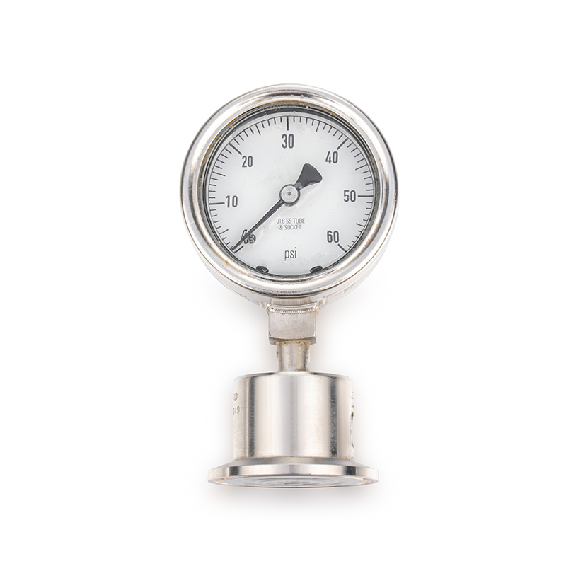 Water Treatment Pressure Gauge with Diaphragm Seal ManufacturersDiaphragm-Seal Pressure GaugeView Product →
A pressure gauge should be isolatable. Install a gauge valve or block valve between the process and the gauge so the gauge can be removed, replaced, or calibrated without draining the system. If the fluid is hazardous, add a bleed or vent valve to relieve trapped pressure before removing the gauge. The valve should be accessible from the same side as the gauge, not hidden behind insulation or a pipe rack.
Protection accessories depend on the location. A snubber or restrictor reduces pressure pulsation from reciprocating pumps, compressors, and fast-acting valves. A siphon protects against steam temperature. A diaphragm seal protects against corrosion, clogging, and hygiene risks. A capillary allows the gauge to be mounted away from vibration, heat, or a cramped pipe. Liquid filling reduces pointer flutter and wear in vibrating service.
Place it close to the process tap so the gauge can be serviced without a full shutdown. Use a valve rated for the process pressure and temperature.
Use it on pulsating lines, especially near reciprocating pumps and compressors. It smooths the pressure signal and extends gauge life.
Use it on steam service. Fill the siphon with condensate before commissioning so the gauge is not exposed to live steam.
Use it for corrosive, viscous, or solids-containing fluids. Keep the seal close to the gauge and match the diaphragm material to the process.
Service access is part of location. Leave at least 300 mm around the gauge for a wrench and a hand. The operator should be able to see the dial, reach the isolation valve, and read the unit label without removing a guard. If the gauge is outdoors, protect it from direct rain, ice, and sun. If it is in a washdown area, use an appropriate enclosure and a sealed connection.
Different systems have different pressure reference points. The following locations are common starting points, not universal rules. Always check the process diagram, control philosophy, and local code requirements.
In a water treatment system, place a gauge at the pump discharge, before and after filters, before and after a pressure-reducing valve, and on the concentrate or return line if the process uses one. For a reverse osmosis system, inlet pressure, interstage pressure, and concentrate pressure help diagnose fouling and scaling. For a domestic water system, install a gauge near the main shutoff valve or on a hose bibb branch that is not flowing. For a water purifier, a gauge before the filter shows supply pressure; a gauge after the filter shows how much pressure is lost across the element.
Do not install a water gauge at the lowest point of a dead leg where sediment can collect. If the water contains particles, use a diaphragm seal or a gauge with a large, clean passage. In cold climates, protect the gauge and connection from freezing. A frozen connection can crack and release water under pressure.
In refrigeration and air conditioning, gauges are typically connected at service ports on the suction, discharge, and liquid lines. The suction gauge belongs on the low-pressure side, close to the compressor suction service valve but after any accumulator or suction filter. The discharge gauge belongs on the high-pressure side, close to the compressor discharge but before the condenser. The liquid line gauge helps check subcooling and pressure drop across the filter drier.
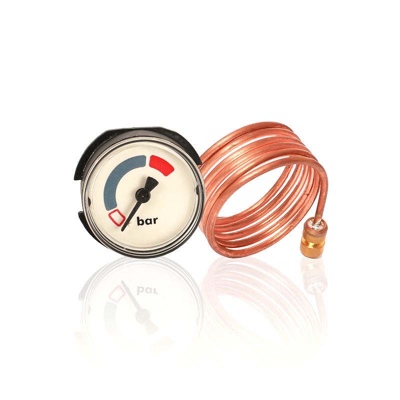 HVAC Capillary Pressure Gauge ManufacturersHVAC capillary pressure gauges transmit pressure signals to remote locations through a thin capillary tube, which can be used in scenarios where installation space is ...View Product →
A capillary gauge or remote-reading gauge is useful when the service port is in a tight cabinet or near a hot compressor. If the system uses a differential pressure gauge, install it across the filter or coil with equal-length tubing and proper high and low ports. Keep the tubing away from hot surfaces and sharp edges. Purge air from liquid lines before taking a reading.
On a steam boiler, the pressure gauge belongs on the top of the boiler shell or on the steam space, not on the water space. It should be connected through a siphon and an isolation valve. The gauge should be visible from the operating floor. A separate gauge on the feedwater line helps confirm pump performance and check the pressure drop across the feedwater valve. Never install a standard gauge directly on a steam line without temperature protection.
In petrochemical service, locate the gauge on the process vessel or line where the pressure represents the reaction or separation condition. Use a side tap on liquid lines and a top tap on gas lines. For corrosive, toxic, or polymerizing fluids, use a diaphragm seal or a full stainless steel gauge with the correct wetted parts. Keep the impulse line short and sloped so it can drain or vent. Avoid low pockets where two-phase fluid can collect.
In medical oxygen systems, place the gauge at the regulator outlet or on the zone valve outlet so staff can verify line pressure. In vacuum systems, place the gauge at the suction canister or at the pump inlet, not where condensate can enter the gauge. In sphygmomanometers, the gauge is located on the cuff inflation circuit, but the calibration reference should be checked at the gauge connection. Medical gauges must be cleanable, accurate, and compatible with oxygen service.
For engine oil pressure, the gauge belongs on the main oil gallery or at the oil filter housing, where it sees pressure after the pump and before the bearings. For tire pressure, the gauge belongs at the valve stem with a proper sealing chuck. For hydraulic systems, place the gauge at the filter outlet, pump outlet, or actuator inlet depending on the diagnostic goal. Use liquid-filled or shock-resistant gauges on vibrating machinery.
On an espresso machine, the brew pressure gauge is usually located on the pump outlet or brew boiler circuit. It should be after the pump and before the group head so the barista sees the pressure that reaches the coffee. A separate steam boiler gauge shows steam pressure. Use food-safe materials and a cleanable connection. Avoid mounting the gauge where milk, cleaning chemicals, or water can pool around the connection.
| Application | Preferred gauge location | Common wrong location | Why it matters |
|---|---|---|---|
| Pump discharge | Close to pump outlet, after check valve, before first restriction | Far downstream after long piping run | Long runs dampen pressure changes and hide pump problems |
| Filter monitoring | One gauge before filter, one after filter | Only one gauge on the outlet | Differential pressure shows loading; a single gauge cannot |
| Water main | Near main shutoff valve or non-flowing branch | Lowest dead leg with sediment | Sediment blocks the connection and causes slow response |
| HVAC refrigerant | Service port on suction, discharge, and liquid lines | At sharp bends or on vibrating compressor shell | Vibration and turbulence shorten gauge life |
| Steam boiler | Top of boiler with siphon and isolation valve | Direct connection without siphon | Steam temperature can damage the Bourdon tube |
| Chemical reactor | Side tap with diaphragm seal, short impulse line | Long dead leg with trapped process fluid | Dead legs can clog, corrode, or create false pressure |
| Medical oxygen | Regulator or zone valve outlet, visible to staff | Hidden behind equipment or near condensate | Staff need immediate pressure verification |
| Compressed air | Receiver tank or after dryer and filter | Before the dryer or in a low pocket | Condensate and oil can enter the gauge |
Most pressure gauge errors come from location, not from the gauge itself. These are the mistakes seen most often in the field.
Fix the location before changing the gauge. A higher-accuracy gauge in the wrong place will still give the wrong answer. A lower-cost gauge in the right place can provide years of stable service.
Once the location is confirmed, the gauge specification becomes clearer. The location determines the required connection type, case style, accuracy, and protection.
A 40 mm or 50 mm gauge fits a compact panel, coffee machine, or small regulator. A 60 mm gauge is a common compromise for local indication. A 100 mm or 150 mm gauge is easier to read from a distance and is preferred for process control. A radial connection mounts directly on a pipe or valve. A back connection mounts through a panel. A capillary connection moves the dial away from the tap.
Dry cases are suitable for clean, stable service. Liquid-filled cases reduce pointer flutter and protect the movement from vibration. If the gauge is mounted on a compressor, pump, or mobile equipment, liquid filling is often worth the extra cost. If the gauge is in a washdown or outdoor area, choose a case with appropriate sealing.
For general indication, 2.5 percent of full scale is common. For control or testing, 1.6 percent or 1.0 percent may be needed. Select a range so normal operating pressure falls in the middle half of the dial. A gauge that runs at the top of its range wears faster and is less accurate. A gauge that runs at the bottom of its range may not show small changes.
Field tip: Write the location and service on the gauge tag, not only in the maintenance system. The next technician should know whether the gauge reads pump discharge, filter outlet, or boiler steam pressure without tracing the pipe.
In water, each 1 m of vertical offset between the tap and gauge adds about 0.098 bar, or roughly 1.4 psi. The error grows with height, so a gauge mounted far below a tap can read high even when the process pressure is correct.
On a clean water line, place the gauge on a side tap of a straight horizontal run, near the main shutoff valve or on a non-flowing branch. If you need to monitor a filter, install one gauge before the filter and one after it. Avoid a top tap where air can collect and a bottom tap where sediment can settle. Keep the gauge at the same elevation as the tap when possible, because water head changes the reading.
Yes, but the reading will include the pressure of the liquid column. In water, a gauge 3 m below the tap will read about 0.29 bar, or roughly 4.3 psi, higher than the tap pressure. If the gauge must be below the tap, correct the reading for elevation or use a remote seal with a capillary designed for that installation. For gas and steam, the effect is different and depends on condensate in the line.
It depends on what you want to measure. A gauge before a control valve shows upstream supply pressure. A gauge after the valve shows the controlled downstream pressure. For a filter, gauges before and after show differential pressure. For a pump, a gauge at the discharge after the check valve shows pump load. Avoid placing the tap directly against a valve body, because turbulence can create a fluctuating reading.
Place the main gauge on the receiver tank or after the dryer and filter, where it shows the pressure available to the system. A gauge at the compressor discharge, before the aftercooler, shows compressor load but may be hot and pulsating. Use a snubber or restrictor on the discharge gauge. For filter monitoring, install gauges before and after the filter to see pressure drop.
On a steam boiler, install the gauge on the steam space, usually at the top of the boiler shell. Use a siphon or pigtail between the boiler and the gauge to protect it from high temperature. Add an isolation valve for service. The gauge should be visible from the operating floor. On a hot water boiler, place the gauge on the supply or return line according to the control strategy and local code.
For a centrifugal pump, the suction gauge goes on the suction line close to the pump inlet, and the discharge gauge goes on the discharge line after the check valve. Keep both taps on straight runs. A suction gauge helps detect cavitation risk and clogged strainers. A discharge gauge shows pump performance and system resistance. Use snubbers if the pump creates pulsation.
For liquid, the side of the pipe is usually best because it avoids trapped air at the top and sediment at the bottom. For gas, the top or upper side is best so condensate can drain away. For steam, use the top with a siphon. For slurry, use a side tap with a diaphragm seal. The correct choice depends on the fluid and the risk of trapped material.
For a standing operator, the center of the dial should be about 1.5 m to 1.8 m above the floor or platform. For a seated operator, 1.1 m to 1.4 m is more comfortable. Small gauges need to be closer to eye level than large gauges. If the correct process location is too high or too low, use a capillary or remote display rather than compromising the measurement point.
Many gauges can be mounted in different positions, but the dial should remain readable and the connection should not be over-stressed. For liquid-filled gauges, follow the manufacturer's mounting instructions because the fill level and vent can affect performance. A horizontal pipe with a vertical gauge is common; a gauge mounted sideways on a vertical pipe is also common if the dial faces the operator. Avoid unusual angles that trap air or make the pointer hard to read.
In an HVAC or refrigeration system, gauges are connected at service ports on the suction, discharge, and liquid lines. The suction gauge is on the low-pressure side near the compressor suction service valve. The discharge gauge is on the high-pressure side near the compressor discharge. The liquid line gauge helps check subcooling and filter drier pressure drop. Use a capillary gauge if the service port is hard to reach.
Install one gauge upstream of the filter and one downstream. The difference between the two readings is the pressure drop across the filter. When the drop reaches the manufacturer's recommended limit, change or clean the filter. A single gauge on the downstream side cannot show loading unless the upstream pressure is known and stable.
Place the gauge at the regulator outlet or zone valve outlet, where clinical staff can see the pressure supplied to the line. In vacuum systems, place the gauge at the suction canister or pump inlet. Use oxygen-compatible materials and clean assembly practices. The gauge should be visible, secure, and protected from liquid ingress.
Fire sprinkler systems typically require gauges at the main drain and at other points specified by the applicable fire code. The gauge connection should not be smaller than the code minimum, often 1/4 inch. Gauges are used to verify system pressure, check for fluctuations, and support maintenance. Always follow the local fire code and the authority having jurisdiction.
Install the gauge close enough to see pump discharge pressure but far enough to avoid severe pulsation and vibration. A tap on a straight run after the check valve is common. If the pump produces strong pulsation, use a snubber, restrictor, or liquid-filled gauge. The exact distance depends on pipe size, pump type, and system layout. Avoid mounting directly on the pump casing unless the gauge is designed for that service.
A siphon is needed for steam service and other high-temperature applications where the gauge would otherwise be exposed to damaging heat. The siphon creates a water seal that protects the Bourdon tube. For hot water or hot oil, a siphon or cooling element may also be required. For ambient-temperature water and gas, a siphon is usually not necessary.
Yes, but an end-of-pipe location can trap air, collect sediment, or create a dead leg. If the pipe is a dedicated gauge connection, keep it short and slope it to drain or vent. Use a diaphragm seal for dirty or viscous fluids. Do not use a long, closed branch as a gauge connection, because it can slow response and give a false steady reading.
On an espresso machine, the brew pressure gauge is usually located on the pump outlet or brew boiler circuit, after the pump and before the group head. It shows the pressure that reaches the coffee puck. A separate steam boiler gauge shows steam pressure. Use food-safe materials and keep the connection clean. Avoid mounting the gauge where milk or cleaning chemicals can pool around the threads.
Location determines what pressure the gauge sees and how stable that signal is. Selection determines whether the gauge can survive the pressure, temperature, fluid, vibration, and environment at that location. A correct gauge in the wrong location can read low, high, or slow. A correct location with the wrong gauge can fail early or create a safety risk. Both decisions must work together.
Review the location after any process change, pump replacement, piping modification, or control upgrade. Also review it after repeated gauge failures or unexplained readings. A location that worked for one duty cycle may not work after flow rates, fluid properties, or operating pressure change. Keep a simple tag or drawing that shows what each gauge measures.
Do not move the gauge to a convenient but wrong point. Instead, use a remote capillary, a pressure transmitter with a local display, a larger dial, or a mirror. A back-connection gauge can also help when the pipe runs overhead. If the gauge must be viewed from a distance, choose a larger dial and a higher-contrast face. Readability should support the measurement point, not replace it.
Before the system is started, verify one more time that the gauge is reading the pressure you think it is reading. Close the isolation valve, open the bleed, confirm the zero or reference point, and then bring the gauge back into service slowly. A pressure gauge is a small instrument, but its location decides whether the number on the dial is a fact or a guess.

+86-15105800222
+86-15105800333


Shuangtang Industrial Zone,Liuheng Town , Putuo District, Zhoushan City,Zhejiang Province,China
We will reply to you within 12 hours after receiving the inquiry on working days. Or, give us a call.
The information provided on this website is intended for use only in countries and jurisdictions outside of the People's Republic of China.
Copyright © Zhoushan Jiaerling Meter Co., Ltd. All Rights Reserved.
 Wholesale Pressure Gauge Factory
