 English
 中文简体
中文简体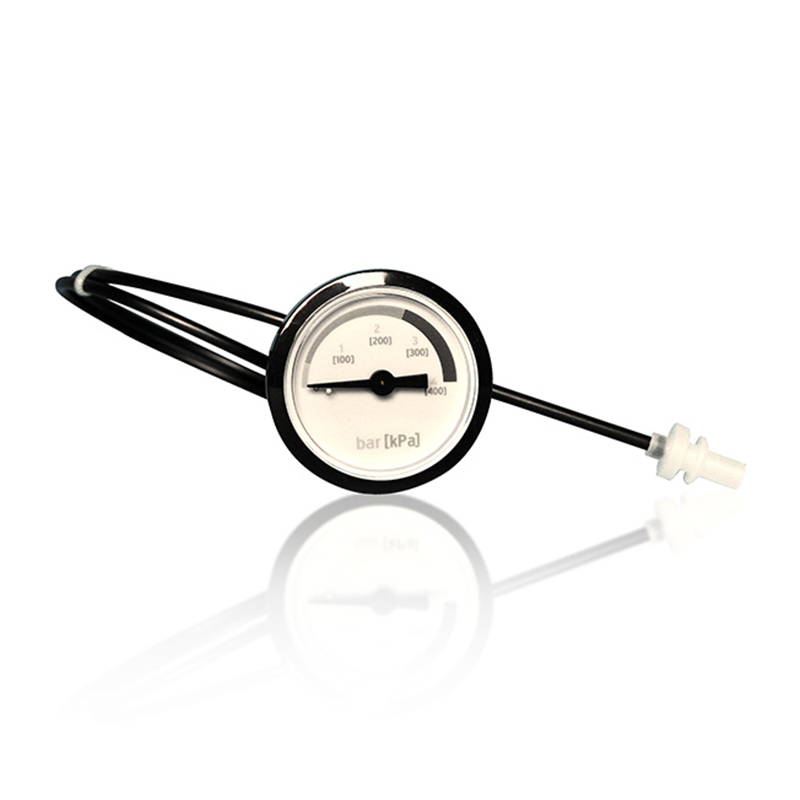


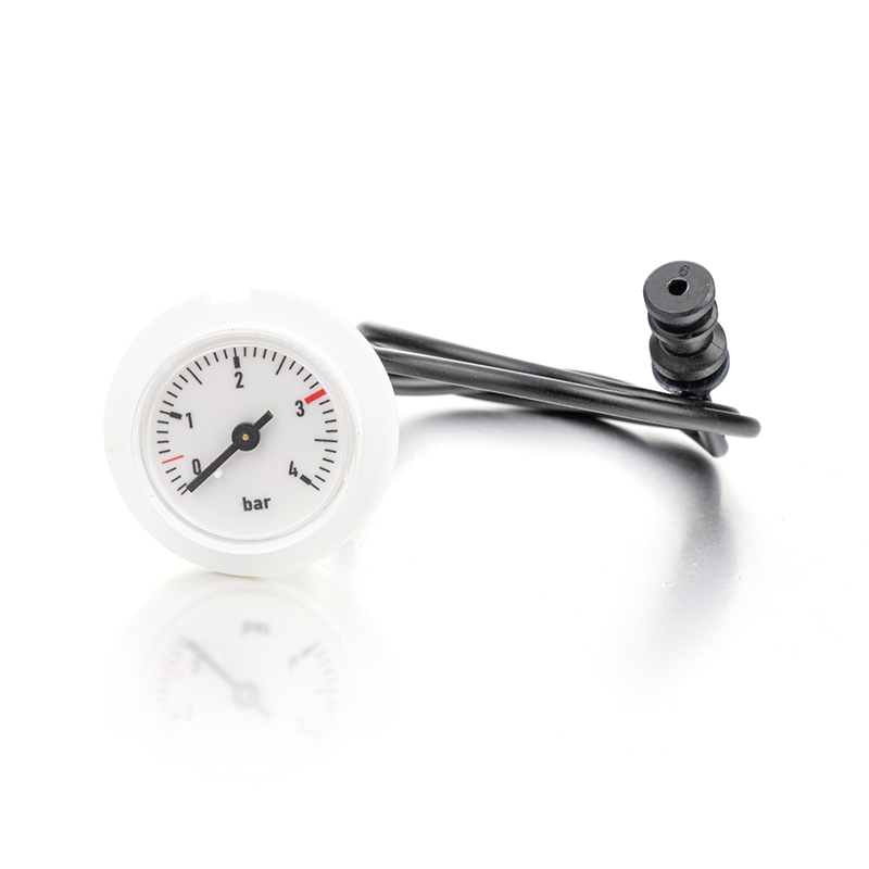
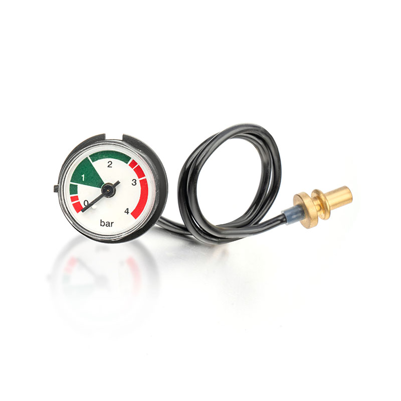

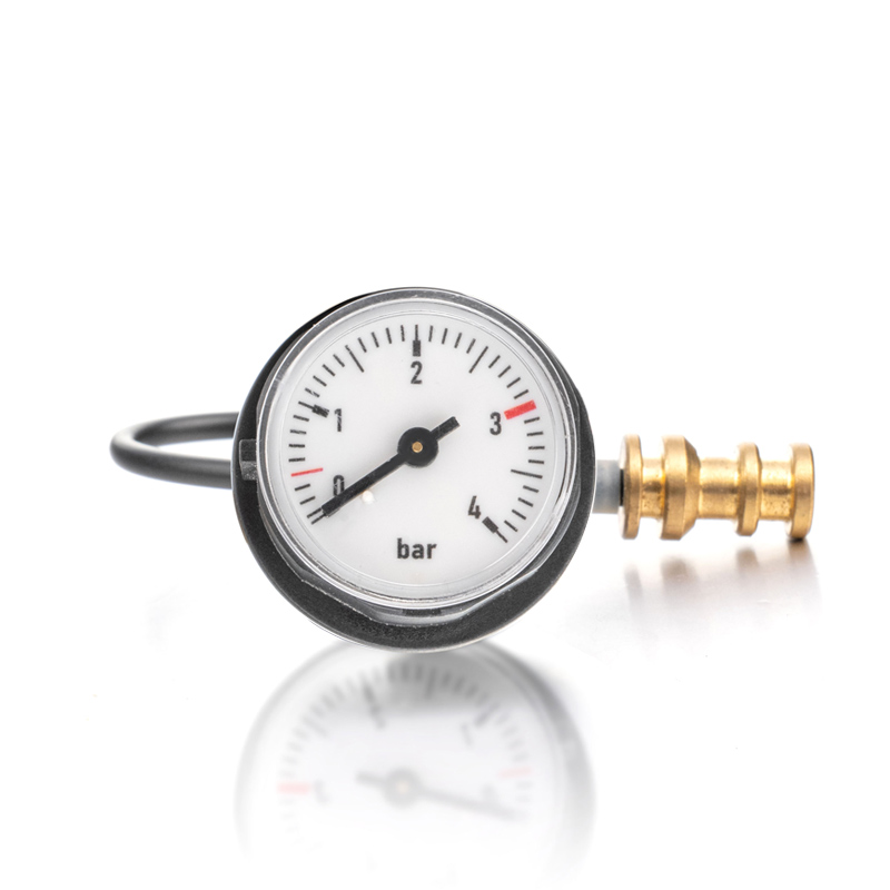
Call us
+86-15105800222
+86-15105800333


A maintenance technician once checked a hot-water boiler with a pressure gauge held loosely against the valve. The reading showed 1.2 bar, so he assumed the system was safe. A second check with the gauge pressed squarely and held until the needle stabilized showed 2.8 bar—well above the relief valve setting. The difference was not a faulty gauge; it was incorrect technique.
Properly using a pressure gauge is more than attaching it to a port and reading the needle. You need to understand what the gauge is measuring, how the measuring element responds, how to position the gauge, and how to interpret the dial without parallax error. This guide walks through the practical side of pressure measurement, from basic principles to step-by-step operating procedures for common gauge types.
A pressure gauge measures the force that a fluid or gas exerts on a unit area. Most industrial gauges display gauge pressure, which means the reading is relative to atmospheric pressure. If a system is open to the atmosphere, the gauge reads zero. If pressure is lower than atmospheric pressure, the needle moves to the vacuum side of the dial.
Three terms are essential when using a gauge:
Mechanical pressure gauges rely on an elastic element that deforms under pressure. A Bourdon tube straightens as pressure increases, a diaphragm bows outward, and a capsule expands. That motion is transferred through a linkage to a pinion and gear, moving the needle over a calibrated scale. Knowing the element inside the gauge helps you understand why some gauges react slowly, why some are better for corrosive media, and why overpressure can permanently damage the mechanism.
Different applications require different sensing elements and case designs. Choosing the wrong type is one of the most frequent causes of inaccurate readings and early gauge failure. Below are the main categories used in industrial and commercial settings.
The most common pressure gauge design. A curved tube unwinds under pressure, moving the needle. Durable, low-cost, and suitable for most industrial fluids and gases.
A flexible diaphragm deflects with pressure. Used for lower pressures, viscous fluids, slurries, and media that could clog a Bourdon tube. Often paired with a diaphragm seal.
Two corrugated membranes welded together. Designed for very low pressures, drafts, and gas applications where you need fine resolution at near-atmospheric pressure.
Use a pressure sensor and an electronic display. Offer high accuracy, multiple units, and no parallax error, but need battery power and are less resistant to extreme vibration.
There are also specialty gauges such as tire-pressure gauges, refrigerant manifold gauges, submersible depth gauges, and differential pressure gauges. Their operating principle is the same, but the connection, scale, and case design are adapted to a specific media or environment.
Reading a gauge sounds simple, but small errors can lead to wrong decisions. The most common mistake is reading the dial from an angle, which causes parallax error. To avoid this, position your eye directly perpendicular to the dial face. If the gauge has a pointer with an anti-parallax mirror, align the pointer with its reflection.
Every gauge shows its range in pressure units such as psi, bar, kPa, or MPa. Some gauges have two scales printed on the same dial. Before taking a reading, confirm which unit is relevant to your system. For example, a dual-scale gauge might read from 0 to 200 psi and 0 to 14 bar. Reading the wrong scale is a common and costly error.
Accuracy class tells you the maximum deviation from true pressure, expressed as a percentage of the full scale. A class 1.6 gauge with a 0–10 bar range has a maximum error of ±0.16 bar anywhere on the dial. The table below shows typical classes and their tolerances for a 0–10 bar gauge.
| Accuracy Class | Maximum Error (% of full scale) | Maximum Error on 0–10 bar Range | Common Application |
|---|---|---|---|
| 0.25 | ±0.25% | ±0.025 bar | Calibration, laboratory |
| 0.6 | ±0.6% | ±0.06 bar | Process control |
| 1.0 | ±1.0% | ±0.10 bar | Industrial monitoring |
| 1.6 | ±1.6% | ±0.16 bar | General service |
| 2.5 | ±2.5% | ±0.25 bar | Non-critical indication |
Use a gauge with a range where your normal working pressure falls between 25% and 75% of the full scale. That gives the best accuracy because the error is a fixed percentage of full scale, not of the measured value.
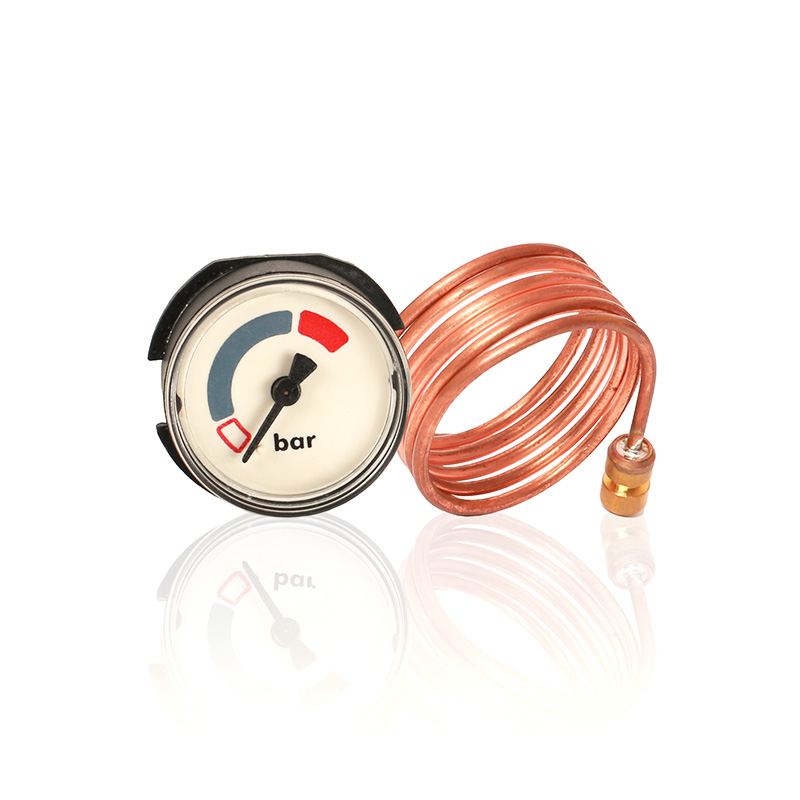 HVAC Capillary Pressure Gauge for Remote InstallationThis capillary-type gauge suits HVAC systems where limited space, vibration, or high temperature makes direct mounting impractical. Its corrosion-resistant materials and flexible capillary deliver stable, accurate readings in challenging environments.View Product →
The correct procedure depends on whether you are taking a manual reading with a portable gauge or monitoring a system with a permanently installed gauge. These steps cover the most frequent situations in workshops, plants, HVAC service, and vehicle maintenance.
Digital gauges are easier to read but still require correct connection and use. Turn the gauge on before connecting, and allow it to zero with the vent port open to atmosphere. Connect to the system, open the valve, and wait for the display to stabilize. Digital gauges are sensitive to low battery voltage, which can cause drift. Check the battery status if the reading jumps or does not settle.
Tire gauges are a specialized form of pressure gauge. For accurate readings, check tires when they are cold, since driving heats the air and raises pressure. Remove the valve cap, press the gauge squarely over the valve stem, and push down quickly to minimize air loss. The hiss stops when the seal is complete. Hold for a second, then remove and read. Compare the reading to the manufacturer's recommended PSI, usually found on a sticker in the driver's door frame.
Refrigerant gauges measure both low-side and high-side pressures. Connect the low-pressure hose (blue) to the suction line and the high-pressure hose (red) to the liquid line. The center yellow hose connects to the vacuum pump or refrigerant cylinder. Open the manifold valves only after both hoses are confirmed tight. Read the gauge while the system is running, and compare the values to the pressure-temperature chart for the exact refrigerant type. If you work on air-conditioning refrigerant systems, always use a gauge rated for the specific refrigerant to avoid safety issues.
Diaphragm-sealed gauges protect the internal sensing element from corrosive, viscous, or clogging fluids. The diaphragm is welded to a flanged connection and filled with a transmission fluid. When using this type, do not remove the filling plug. The chamber between the diaphragm and the connection must remain full. Check the system and the gauge flanges for leaks, because any loss of fill fluid causes sluggish or false readings. These gauges are common in water treatment lines where solids and scale could otherwise block a standard gauge.
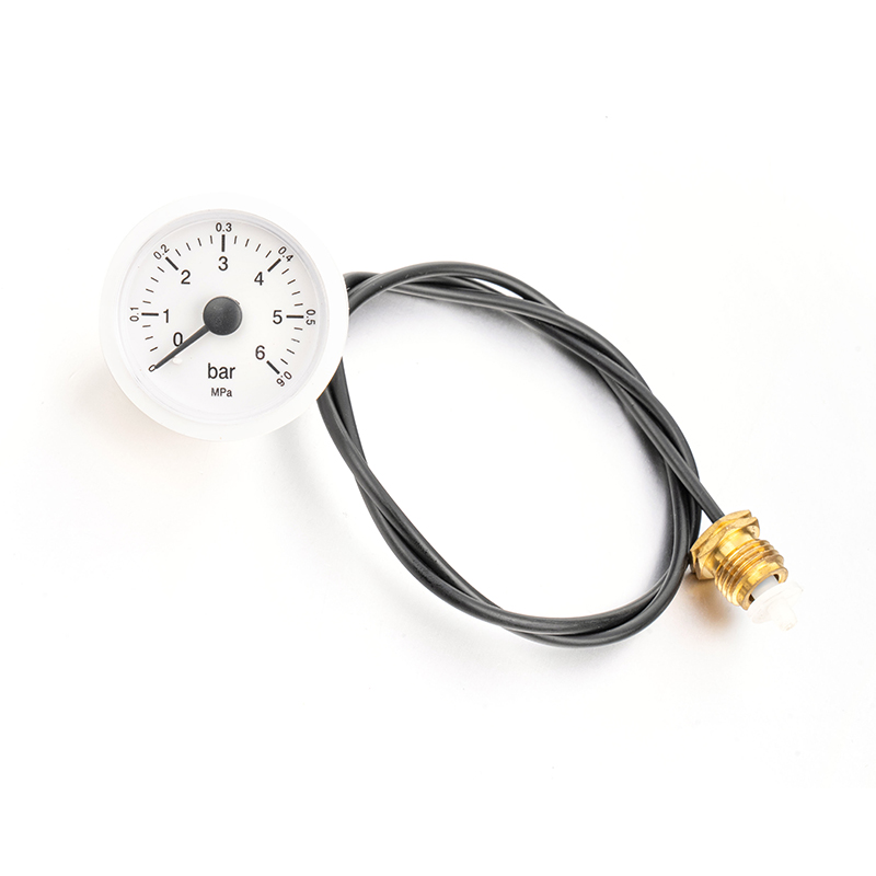
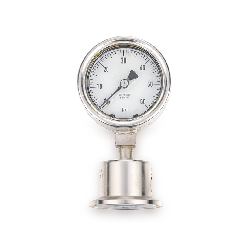 Water Treatment Pressure Gauge with Diaphragm SealA diaphragm-sealed gauge protects the sensing element from corrosive, viscous, or clogging fluids, making it well suited for water treatment lines with solids or scale. Maintaining proper fill fluid ensures accurate, reliable readings.View Product →
Correct installation affects both accuracy and service life. A poorly located gauge can vibrate, overheat, or become difficult to read. Keep these points in mind before mounting a gauge permanently.
Use a thread sealant compatible with the system media. PTFE tape is common for water and compressed air, but some chemicals require liquid sealants. Tighten the connection firmly, but avoid overtightening a brass or plastic fitting. Backing up the connection with a second wrench prevents the gauge internals from twisting.
For systems that pulse, such as reciprocating pumps, add a dampening device. A pulsation snubber restrictor, an oil-filled case, or a diaphragm seal with a fill fluid reduces needle flutter and extends gauge life.
Most pressure gauge failures are not manufacturing defects; they are installation and operating errors. These are the most frequent problems we see on site:
No mechanical gauge stays accurate forever. Wear, vibration, temperature cycling, and pressure spikes slowly change the linkage geometry. A regular calibration program catches these changes before they cause a safety or quality problem.
Calibration compares the gauge reading to a known reference pressure standard, usually a deadweight tester or a calibrated master gauge. For a simple field check, you can compare a suspect gauge to a new calibrated gauge connected to the same system. The readings should not differ by more than the sum of their accuracy classes.
Do not open a mechanical gauge for adjustment unless you have the correct tools and training. Most gauges have an adjustable pointer that can be reset to zero, but a bent link or worn pinion cannot be fixed by adjusting the pointer. Replacement is often more economical than repair.
Regular maintenance includes cleaning the exterior lens, checking the case for damage, replacing degraded gaskets, and verifying the pressure-relief function on sealed cases. For gauges in wet or process service, establish a calibration interval based on the manufacturer's recommendation and the severity of the application. A practical guide to keeping gauges reliable can be found in our article about pressure gauge maintenance and calibration tips.
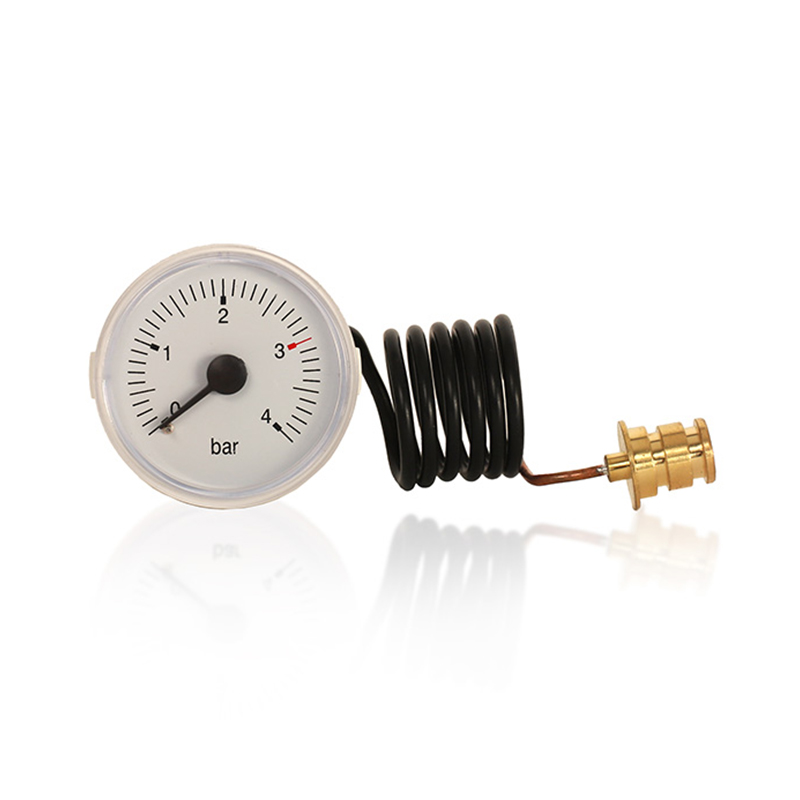
 Capsule Pressure Gauge for Sensitive Pressure MeasurementCapsule gauges offer high sensitivity and fast response, resisting temperature, low pressure, and shock. They provide reliable measurement for liquids and gases in industrial processes, supporting accurate calibration and maintenance practices.View Product →
Selecting the right gauge is a matter of matching the instrument to the process media, pressure range, environment, and connection requirements. The decision is not only about accuracy; it is about reliable operation over the expected lifespan.
Copper alloy wetted parts are suitable for oil, air, and non-corrosive fluids. Stainless steel wetted parts are required for acids, caustics, food products, and salt water.
Choose a range where the normal working pressure is in the middle of the scale. A typical recommendation is 25% to 75% of full scale, never above 90% for steady pressure.
Outdoor or washdown locations need an IP-rated enclosure. Vibration-prone machinery benefits from a liquid-filled gauge.
Bottom connection is standard for direct mounting. Back connection with a flange is used for panel mounting. The thread size must match the process port.
For low-pressure gas or filtered systems, a capsule pressure gauge provides the fine resolution needed for accurate readings. For high-vibration industrial circuits, an oil-filled gauge with a stainless steel case is a better choice. When the media contains particles or is corrosive, a diaphragm seal prevents the gauge inlet from clogging.
The table below summarizes the primary selection criteria for common applications.
| Application | Media | Recommended Gauge | Key Requirement |
|---|---|---|---|
| General compressed air | Air, dry | Bourdon tube, brass case | Low cost, visible dial |
| Water treatment line | Water with particles | Diaphragm-sealed gauge | Resistance to clogging |
| Steam boiler | Steam, high temperature | Bourdon tube with siphon | Temperature isolation |
| Corrosive chemical | Acid or caustic | Stainless steel wetted parts | Corrosion resistance |
| Low-pressure gas duct | Air or gas | Capsule gauge | High sensitivity at low pressure |
| Reciprocating pump | Oil or water | Oil-filled gauge | Vibration damping |
Gauge accuracy is defined by standards such as EN 837-1 for Bourdon tube gauges, ASME B40.100, and the Japanese JIS B7505 series. The accuracy class number is the maximum error as a percentage of full scale. For example, a class 1.6 gauge with a range of 0 to 16 bar has an error limit of ±0.256 bar.
Keep in mind that accuracy class does not include the error caused by the user. Parallax error alone can contribute more than 0.5% of full scale if you read from a steep angle. A higher-precision gauge with a smaller dial might not improve overall measurement accuracy if the user cannot see the needle clearly.
Temperature also affects gauge accuracy. The standard reference temperature is usually 20°C. When the ambient or process temperature moves away from that reference, the elasticity of the Bourdon tube changes, adding a temperature error. The chart below illustrates the approximate additional error for a typical dry gauge.
If you need a more detailed comparison of gauge types and their applications, review our selection guide on understanding pressure gauges, types, and how to choose. It provides a deeper look into specifications such as ingress protection and wetted material.
Check the accuracy class printed on the dial. For general industrial use, class 1.6 is common. If your process requires tighter control, choose class 0.6 or 0.25. Also compare the gauge against a calibrated master gauge at several points across the scale.
Vibration usually comes from pulsating flow, such as a reciprocating pump or a compressor. Installing a snubber, an oil-filled case, or a slightly longer connection line will dampen the movement. If possible, place the gauge farther from the source of pulsation.
There is no universal interval. Critical safety gauges may need calibration every three months, while a stable air-line gauge might be fine for two to three years. Start with annual calibration, then adjust based on drift you see during comparisons.
Sometimes an adjustable zero error can be corrected by moving the pointer at zero pressure. But if the reading is inconsistent, the link may be bent or the Bourdon tube weakened. In that case, replacement is safer than repair.
Use a dry gauge for clean, vibration-free environments where you want maximum readability. Use a liquid-filled gauge where vibration, pulsation, or condensation is present. The liquid also lubricates the movement and prolongs life.
A pressure gauge shows pressure locally with a needle or digital display. A pressure transmitter converts pressure into an analog or digital electrical signal for remote reading in a controller or PLC. Both can use a similar sensing element, but the output differs.

+86-15105800222
+86-15105800333


Shuangtang Industrial Zone,Liuheng Town , Putuo District, Zhoushan City,Zhejiang Province,China
We will reply to you within 12 hours after receiving the inquiry on working days. Or, give us a call.
The information provided on this website is intended for use only in countries and jurisdictions outside of the People's Republic of China.
Copyright © Zhoushan Jiaerling Meter Co., Ltd. All Rights Reserved.
 Wholesale Pressure Gauge Factory
