 English
 中文简体


Call us
+86-15105800222
+86-15105800333


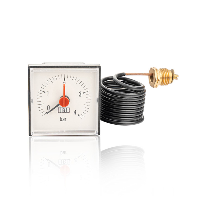
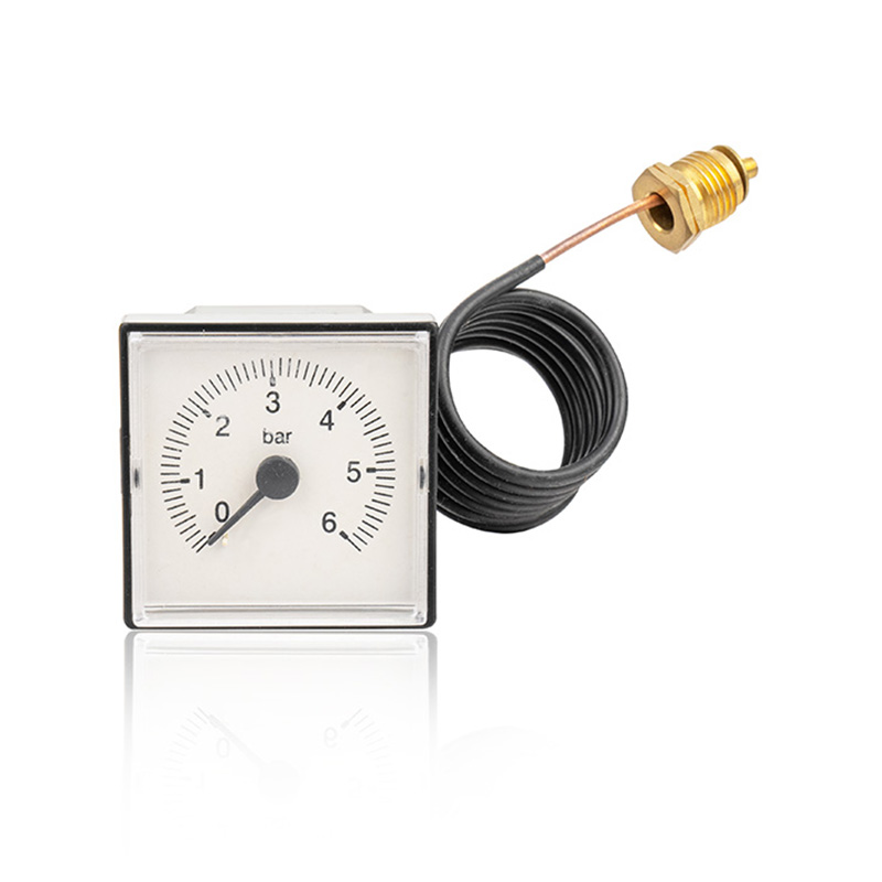
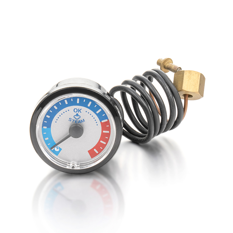
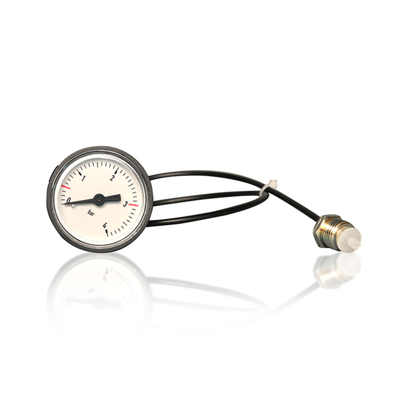
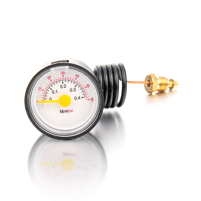
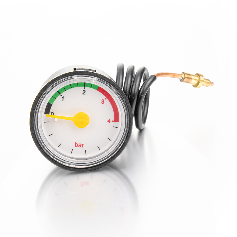
 Y40 Compact 40 mm Pressure GaugeA compact 40 mm nominal pressure gauge with multiple ranges and connection and case material options for industrial and laboratory pressure monitoring.View Product →
The short answer is simple: a mini pressure gauge described as 1.5 inch or 40 mm normally has a 40 mm nominal dial diameter. That number refers to the dial size class, not the outside diameter of the case, not the threaded connection, and not the panel hole. If you are replacing an existing gauge, ordering by "1.5 inch" alone is not enough. The dimensions that decide whether the gauge fits are the case outside diameter, bezel profile, body depth, stem length, thread type, mounting position, and the clearance around the connection.
A 40 mm gauge is often chosen because the equipment has a small panel, a compact manifold, a coffee machine, a medical device, a water purifier, or a service tool where a 50 mm or 63 mm gauge would be too large. That space saving has a cost: the scale is shorter, the printing is finer, and the tolerance stack around the case and thread becomes more important. A 0.5 mm difference in bezel height or a thread that looks similar but does not seal correctly can turn a low-cost gauge into a line-side rejection.
The practical rule is to treat "1.5 inch / 40 mm" as the starting point for identification, then confirm four numbers before purchase: case outside diameter, body depth behind the panel, thread specification, and mounting center distance. For a drop-in replacement, also check the hex flats, the distance from the thread shoulder to the dial, and whether the original gauge uses a gasket, O-ring, or tapered thread seal.
A miniature gauge is a stack of dimensions. The dial size tells you the general family; the dimension chain tells you whether it will assemble, seal, and remain readable. The table below uses typical values for a 40 mm class gauge. Treat them as a checklist, not as a universal specification. The supplier drawing controls the actual product.
| Dimension | Typical 40 mm class value | Why it matters | What to confirm |
|---|---|---|---|
| Nominal dial size | 40 mm / 1.5 inch | Sets the product family and scale length. | Is the catalog size nominal or actual? |
| Visible window | About 33 mm to 36 mm | Controls readability and pointer clearance. | Window diameter and lens material. |
| Case outside diameter | About 42 mm to 45 mm | Determines panel clearance and bezel fit. | OD with bezel installed, not bare case. |
| Bezel height | About 3 mm to 6 mm | Affects flush mounting and knob clearance. | Front profile drawing or side view. |
| Body depth | About 20 mm to 28 mm | Must clear internal parts and panel depth. | Depth excluding thread and stem. |
| Stem length | About 10 mm to 15 mm | Controls wrench access and thread engagement. | Thread length and distance to shoulder. |
| Connection thread | 1/8 NPT, M10 x 1, or specified | Wrong thread causes leaks or cross-threading. | Thread standard, pitch, and sealing method. |
| Mounting style | Bottom, center back, lower back, panel | Determines installation orientation and support. | Center back distance and panel cutout. |
| Weight | Often about 50 g to 90 g | Matters on small manifolds and flexible tubing. | Weight with packaging excluded. |
For panel mounting, the cutout is usually more important than the nominal dial size. A snap-in or U-clamp miniature gauge may need a specific hole diameter, flat area, and rear clearance. If the panel already exists, measure the hole, the distance to nearby components, and the available depth behind the panel. Do not assume that every 40 mm gauge uses the same cutout. Some models are direct-mounted through the thread only; others use a bracket, clamp, or panel nut.
Tolerance also deserves attention. A drawing may specify a case diameter with a normal manufacturing tolerance, but the user may be fitting the gauge into a recess with less than 1 mm clearance. In that situation, ask for the actual drawing and a sample check. The lowest-risk purchase is not the cheapest 40 mm gauge; it is the one whose critical dimensions are documented and repeatable from lot to lot.
The phrase "1/8 inch thread" is not specific enough for a pressure gauge. A 1/8 NPT male thread, a 1/8 BSPT thread, and an M10 x 1 straight thread can all appear on miniature pressure instruments, and they are not interchangeable. The difference is small enough to look correct at a glance and large enough to leak, crack a port, or bottom out before sealing.
| Connection | Typical use on 40 mm gauges | Sealing method | Procurement risk |
|---|---|---|---|
| 1/8 NPT | Very common on compact air, water, oil, and service gauges. | Taper thread; sealant or tape applied correctly. | Can be confused with 1/8 BSPT. Over-tightening can split a small port. |
| M10 x 1 | Common on compact equipment and imported machinery. | Straight thread with gasket, O-ring, or sealing washer. | Missing or incorrect seal can cause a leak even when the thread fits. |
| 1/4 NPT | Less common on 40 mm, more common as size increases. | Taper thread with suitable sealant. | Body clearance may be tight even if the thread is correct. |
| Custom or adapter thread | Equipment-specific ports and OEM assemblies. | Depends on drawing and mating part. | Adapters add length and can change gauge orientation. |
Mounting style creates a second layer of fit risk. A bottom-mount gauge sits vertically on a pipe or manifold and needs wrench clearance below the case. A center-back gauge mounts through the rear of a panel or bracket and needs a straight path behind the panel. A lower-back gauge places the stem below center, which can solve clearance problems but changes the dial orientation. Panel-mount versions may include a U-clamp, bezel ring, or rear nut. Each style changes the effective depth and the service access.
A 40 mm gauge can be accurate, but the small dial limits how precisely a person can read it. Two gauges may both carry a ±2.5% full-scale accuracy statement and still feel very different on a production line. The difference comes from the range, the number of scale divisions, the pointer width, the printed scale, and the viewing distance. A 0-300 psi range on a 40 mm dial gives the user a short scale with coarse divisions. A 0-100 psi range on the same dial gives a much more usable reading for a low-pressure application.
A common starting point is to select a range about 1.5 to 2 times the normal working pressure. If the equipment runs at 90 psi, a 0-200 psi gauge is usually easier to read and safer than a 0-100 psi gauge with no headroom.
At ±2.5% of a 200 psi full scale, the allowable error is about 5 psi across the scale. The smallest readable division may be larger than the accuracy number suggests. Ask for the scale division and the actual test points.
On a 40 mm dial, crowded dual scales, tiny psi markings, and a thick pointer reduce practical readability. Choose a single scale or a clean dual scale with clear major markings.
Accuracy class also needs context. Miniature gauges are often supplied at ±2.5% or ±4% full scale, depending on the model and application. For a coffee machine extraction check or a compact air line, that may be adequate. For a medical device, a calibration bench, or a safety interlock, the gauge may need a higher specification, a larger dial, or an electrical pressure sensor. The nominal size should follow the measurement task, not the other way around.
Scale readability affects installation decisions. If the gauge is mounted at eye level and read often, a 40 mm dial can work. If it is mounted low, behind a panel, or viewed from an angle, a 50 mm or 63 mm gauge may be the better choice even when a 40 mm unit physically fits. For guidance on units, divisions, and pointer interpretation, this reference on reading a pressure gauge scale is useful for training and incoming inspection.
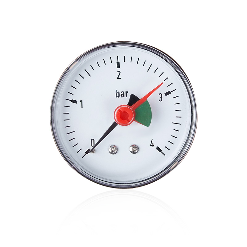 Y50 Mechanical Pressure Gauge for Pneumatic SystemsA 50 mm mechanical pressure gauge for pneumatic and industrial use, with multiple ranges and material options that can improve scale readability over smaller dials.View Product →
A 1.5 inch gauge is not automatically the best choice just because it is small. The correct size is the smallest gauge that gives acceptable readability, service access, and durability for the application. If the panel can accept a 50 mm case, the larger dial often improves scale length, pointer visibility, and range selection without a large cost penalty.
| Nominal size | Typical strength | Typical limitation | Best fit |
|---|---|---|---|
| 40 mm / 1.5 inch | Compact installation, low weight, tight panels, small manifolds. | Shorter scale, finer printing, less space for options such as liquid filling. | Coffee machines, compact medical devices, small water systems, portable tools, embedded equipment. |
| 50 mm / 2 inch | Better readability, more range choices, easier service access. | Requires more panel area and rear clearance. | HVAC service, air compressors, small pumps, general industrial panels. |
| 63 mm / 2.5 inch | Longer scale, better accuracy options, more robust case choices. | Too large for many compact devices; higher weight and cost. | Pumps, process lines, vibration-prone equipment, maintenance panels. |
The 40 mm size is often the right answer when the gauge is a component inside a machine rather than a stand-alone instrument. The 50 mm size is often the better answer when a technician must read the gauge during service. The 63 mm size starts to make sense when the gauge is part of a permanent panel and the reading is used for decisions. This is a practical distinction, not a rule based on price alone.
For pulsation or vibration, size also matters. A larger case can accommodate a more robust movement and sometimes liquid filling. A 40 mm dry gauge may be perfectly acceptable on a stable water line, but a pump discharge with pressure spikes may need a larger case, a restrictor, a snubber, or a liquid-filled model. If the only available space is 40 mm, solve the pulsation problem with the connection and system design rather than expecting the smallest gauge to absorb every pressure spike.
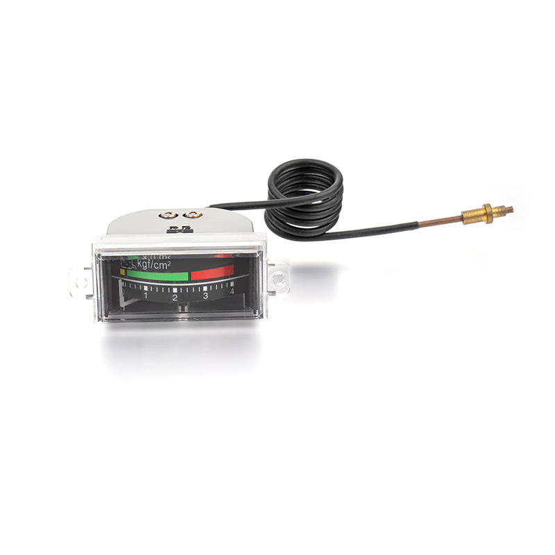
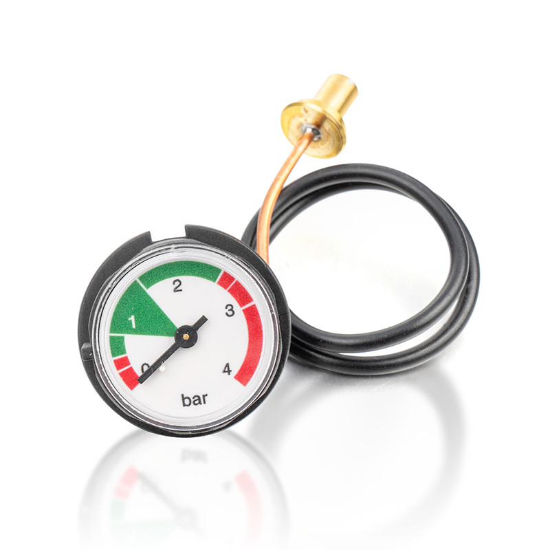
 Coffee Machine Pressure Gauge With Optional BracketA coffee machine gauge for monitoring extraction pressure, available with or without a bracket and in multiple sizes and ranges for household or commercial machines.View Product →
Miniature gauges appear in equipment where the gauge is close to the mechanism, the panel is crowded, or the user needs a quick local indication rather than a control-room signal. The application determines the critical feature. A coffee machine may care about a clean front bezel, a stable extraction pressure, and a bracket that survives vibration. A medical device may care about cleanability, repeatability, and a clear scale. A water purifier may care about corrosion resistance and a leak-free connection. The common thread is that the 40 mm size solves a space problem, but the specification must solve the application problem.
A 40 mm gauge can be a good fit for an OEM product, but the purchasing decision should include the assembly method. If the gauge is threaded directly into a plastic housing, a metal insert or a supported port may be needed. If the gauge is mounted on a bracket, the bracket should locate the gauge without putting bending load on the stem. If the gauge is shipped as a spare part, the packaging and thread protector matter because a small bent stem can make the whole unit unusable.
For compact beverage and appliance equipment, bracket and non-bracket versions are not interchangeable. The bracket changes the mounting position, the panel clearance, and sometimes the orientation of the connection. The same logic applies to back-mount and bottom-mount gauges. The catalog phrase may be similar, but the installation drawing is different. Always match the mounting style to the existing assembly before comparing price.
A clear specification reduces the chance of receiving a gauge that fits the thread but not the panel, or reads the right range but cannot be seen by the operator. The following list is a practical starting point for a 40 mm gauge used in compact equipment.
| Specification item | Weak wording | Better wording | Risk reduced |
|---|---|---|---|
| Thread | 1/8 inch | 1/8 NPT male, tapered, with defined sealant area | Wrong thread, leakage, cross-threading |
| Case size | 40 mm gauge | 40 mm nominal dial, case OD not exceeding the approved drawing limit | Panel interference and bezel mismatch |
| Mounting | Back mount | Center back mount, 1/8 NPT, specified center distance and rear clearance | Poor orientation and assembly interference |
| Accuracy | High accuracy | ±2.5% full scale, tested at agreed points, with recorded readings | Disputes over acceptance and calibration |
| Lens | Plastic lens | Polycarbonate or glass, specified scratch and chemical resistance | Cracking, clouding, and readability loss |
A miniature gauge is easy to inspect if the check is planned around the dimensions that matter. The goal is not to repeat every laboratory test on every unit. The goal is to confirm that the delivered lot matches the approved drawing and that the critical performance points are stable.
Sampling should reflect the risk. A new supplier, a new mold, a new thread insert, or a new dial print deserves a first-article inspection and a larger initial sample. A stable repeat order can move to routine sampling with recorded dimensional and pressure checks. If the gauge is used in a safety-related or medical assembly, the inspection plan should be agreed with the technical owner rather than copied from a general commodity checklist.
No. The 1.5 inch or 40 mm figure is normally the nominal dial size. The case outside diameter is often larger, commonly around 42 mm to 45 mm for many models, but the exact value depends on the bezel and case design. Use the supplier drawing for the case OD, not the nominal dial size.
Common options include 1/8 NPT, M10 x 1, and sometimes 1/4 NPT or a custom thread. The correct choice depends on the mating port and sealing method. A 1/8 NPT and a 1/8 BSPT connection are not interchangeable, even though both may be described casually as 1/8 inch.
Only if the smaller case still gives acceptable scale readability, pointer visibility, and service access. A 40 mm gauge may fit the thread but be harder to read or may not clear the panel bezel. Check case OD, body depth, and the viewing angle before changing size.
Miniature gauges are available in many ranges, from low-pressure and vacuum versions to several hundred psi, depending on the model. Select the range so normal operating pressure sits in the middle of the scale and the maximum system pressure stays within the gauge rating. A 0-300 psi gauge is not automatically better than a 0-100 psi gauge if the system runs at low pressure.
Many miniature gauges are offered at ±2.5% or ±4% full scale, but the actual accuracy class must come from the product specification. On a small dial, reading error can be as important as the declared accuracy. Ask for the scale division and test points if the reading is used for quality decisions.
Some miniature gauges can be supplied with liquid filling or vibration protection, but the options are more limited than on larger cases. For strong pulsation or vibration, consider a larger case, a restrictor, a snubber, or a remote sensor. Do not rely on the smallest gauge to solve a system pulsation problem.
Measure the case outside diameter, body depth, stem length, thread outer diameter, thread pitch if possible, mounting center distance, and panel cutout. Also note the pressure range, units, connection orientation, and whether the original gauge uses a gasket or O-ring. A photo of the installed gauge with a ruler is useful, but it does not replace a drawing.
No. A 40 mm gauge can be well made and repeatable. The size mainly affects scale readability, available options, and the space available for the movement. The quality depends on the specification, materials, assembly control, and calibration, not on the dial diameter alone.

+86-15105800222
+86-15105800333


Shuangtang Industrial Zone,Liuheng Town , Putuo District, Zhoushan City,Zhejiang Province,China
We will reply to you within 12 hours after receiving the inquiry on working days. Or, give us a call.
The information provided on this website is intended for use only in countries and jurisdictions outside of the People's Republic of China.
Copyright © Zhoushan Jiaerling Meter Co., Ltd. All Rights Reserved.
 Wholesale Pressure Gauge Factory
