 English
 中文简体


Call us
+86-15105800222
+86-15105800333


An HVAC pressure thermometer is a single mechanical gauge that shows refrigerant pressure and line temperature together on one dial. It is designed for refrigeration circuits, air conditioners, heat pumps and chillers, where the relationship between pressure and temperature determines whether the system is operating correctly. Instead of attaching a separate pressure gauge and a separate temperature probe to the same pipe, the technician connects one combined instrument and reads both values at the same glance.
The instrument is particularly useful during commissioning, seasonal maintenance and fault diagnosis. On a chiller, for example, the service engineer needs the suction pressure at the evaporator outlet and the saturated evaporating temperature that corresponds to that pressure. If the two readings are taken from different locations, the pressure drop in the piping between them can distort the calculated superheat. Because a pressure thermometer brings both sensors to the same process point, the readings are physically consistent, which is important when you are adjusting an expansion valve or deciding whether the charge is correct.
Beyond accuracy, the combined gauge reduces the number of connections on a refrigerant circuit. Every additional service valve or threaded tee is a potential leak point. One dual-readout instrument means one connection, one gasket and one mounting hole on the panel. That is not a critical consideration on a large industrial machine, but it matters on a residential heat pump, a light commercial condensing unit or a packaged air conditioner where panel space is tight and the factory wants to minimize the number of openings in the casing.
The same logic applies on the service side. A technician carrying one combined meter can move from the suction line to the liquid line without juggling two separate instruments and without reconnecting hoses twice. That is why the HVAC pressure thermometer appears on OEM panels, compressor skids, heat pump outdoor units and refrigeration service carts as standard equipment rather than as an optional add-on.
The pressure side works exactly like a standard refrigerant gauge. Refrigerant enters through the brass or stainless steel socket and acts on a C-shaped Bourdon tube that is closed at the free end. As pressure increases, the tube tries to straighten. That tiny movement travels through a connecting link to a sector gear, which rotates a pinion and turns the main pointer. The mechanism is simple, repeatable and does not require electrical power, which is why mechanical gauges are still preferred in many refrigeration applications where power supplies and electronic sensors add cost and complexity.
The temperature side uses a bimetallic spiral or helix made from two bonded metals with different expansion rates. When the temperature around the sensing element changes, the coil winds or unwinds slightly. This motion is carried to a second pointer or to a small inner dial positioned below the main pointer. The system is completely mechanical, so the temperature indication is available even if the pressure connection is not under pressure, and vice versa.
On a typical dual-scale dial, the outer arc carries the pressure scale in MPa, bar and psi, while the inner arc or an auxiliary window carries the temperature scale in degrees Celsius or Fahrenheit. This layout lets you compare the two values instantly, which is exactly what superheat and subcooling calculations require. The main pointer always shows pressure; the secondary pointer or inner dial shows temperature. On capillary versions, the temperature sensing bulb is mounted remotely and connected to the case by a capillary tube, while the pressure connection remains at the instrument body.
Because the two measuring systems are independent, a fault in one side does not necessarily stop the other side from working. If the bimetallic coil must be replaced, the pressure mechanism can remain in service; if the Bourdon tube is damaged by an overpressure event, the temperature indication usually still responds. This separation is a practical advantage when a gauge is used in a location that is difficult to reach and you want to diagnose which function has failed.
In a refrigeration circuit, pressure and temperature are linked by the refrigerant's saturation curve. For every pressure, there is exactly one saturation temperature. If the actual line temperature is higher than that saturation point, the refrigerant is superheated. If it is lower, the refrigerant is subcooled. The difference between the calculated saturation temperature and the measured line temperature is the single most useful number for checking an expansion valve, verifying the charge or detecting a fouled heat exchanger. That calculation only makes sense when both values come from the same physical location.
To calculate evaporator superheat, you measure the suction pressure at the evaporator outlet, convert it to a saturation temperature using a pressure-temperature chart, and compare that value with the outlet pipe temperature. If the pressure is tapped on the compressor side and the temperature is clamped on the evaporator side, the pressure drop in the suction line makes the saturation temperature appear lower than it should be, so the superheat reading is wrong. A combined instrument eliminates that error because the process connection carries both the pressure and the temperature sensing point.
On the liquid line, the same logic applies to subcooling. The technician compares the liquid pressure at the condenser outlet with the liquid line temperature. If the two readings come from different valves, a restriction in the line or a pressure drop across a filter drier can make the subcooling value look different from the real condition. A dual-readout gauge at the same port removes that variable.
These measurements are not academic. An expansion valve set with false readings will flood the compressor with liquid or cause excessive superheat and low cooling capacity. A system charged with incorrect subcooling data will either suffer from insufficient liquid feed or waste energy through overfeeding. Pairing the two readings in one instrument is the fastest way to get reliable diagnostic numbers on site. For a deeper look at how these readings affect operating cost, see our technical review on how HVAC pressure thermometers improve system efficiency and reliability.
When you choose an HVAC pressure thermometer, the main parameters are the pressure range, the temperature range, the accuracy class, the process connection, the case diameter and the capillary length. These parameters follow the conventions of standard refrigerant gauges, so service teams do not need special tools or adapters to work with them.
| Parameter | Typical Value | Selection Note |
|---|---|---|
| Pressure range | 0 to 2.5 MPa (0 to 350 psi) or 0 to 4.2 MPa (0 to 600 psi) | Choose so that normal operating pressure stays below 75 percent of full scale |
| Temperature range | -40 to +60 °C (-40 to +140 °F) | Matches the standard operating window for refrigeration lines |
| Accuracy class | Pressure: class 2.5 (class 1.6 optional); temperature: ±2 percent of full span | Suitable for service diagnostics and system setup |
| Process connection | 1/4 NPT, 1/4 BSP, or 7/16-20 UNF | The 7/16-20 UNF thread matches standard refrigerant charging hoses |
| Case diameter | 63 mm, 80 mm or 100 mm | Larger diameters improve readability on panels and outdoor units |
| Capillary length | 0.5 m, 1 m, 1.5 m, 2 m or 3 m | Allow slack for routing; avoid sharp bends near the bulb |
| Protection rating | IP52 for panel-mounted, IP65 for outdoor units | Outdoor installations need condensation resistance and sunlight protection |
An R410A system operates at a much higher pressure than an R22 or R134a system. If you install a gauge with a 0 to 2.5 MPa scale on an R410A circuit, the pointer will drive beyond the dial on a hot day and the Bourdon tube may be permanently deformed. The scale is fixed at the factory and cannot be changed in the field, so the refrigerant type must be stated when ordering. For R134a and low-pressure chillers, a 0 to 1.6 MPa range gives better readability because the working pressure sits closer to the middle of the dial.
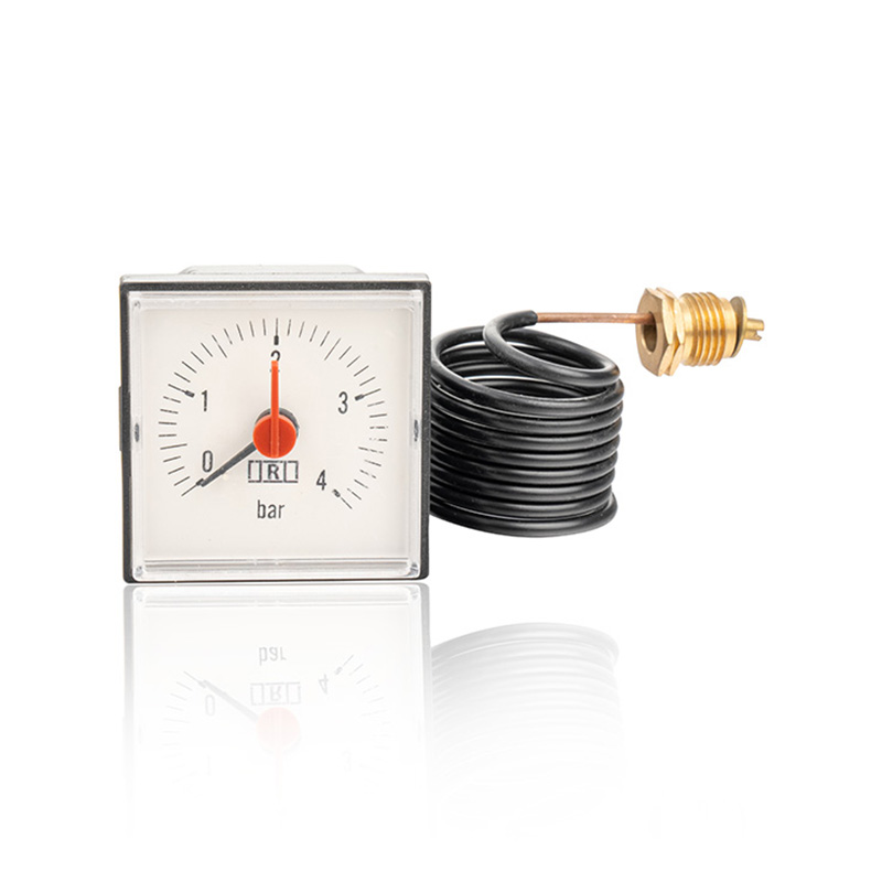
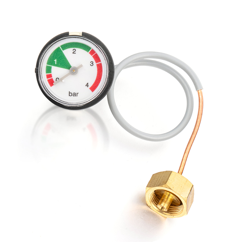
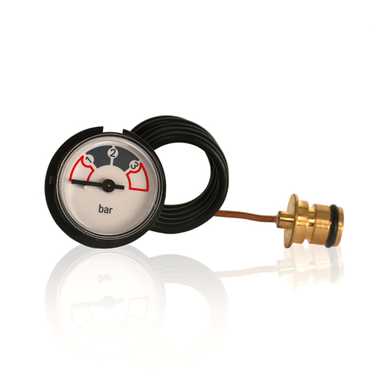
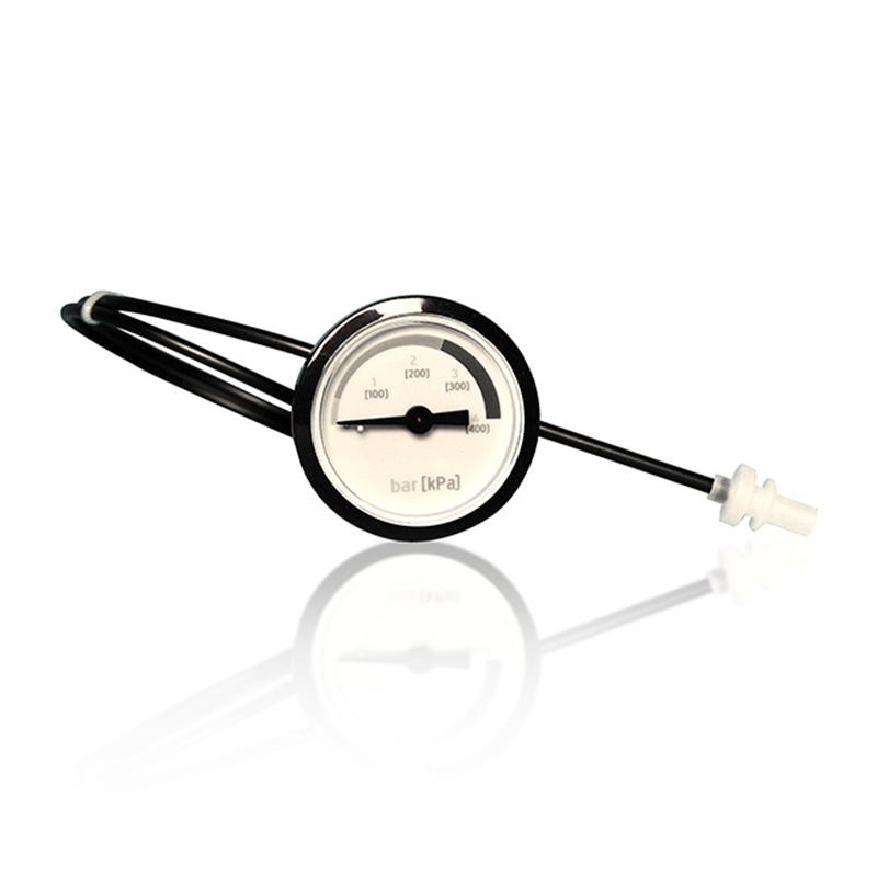
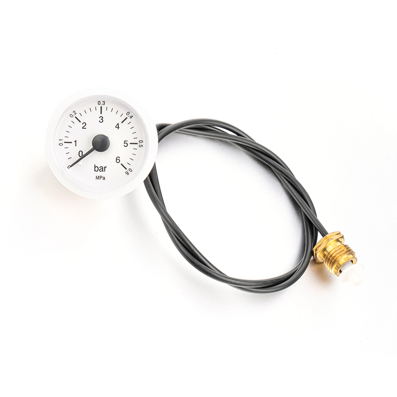
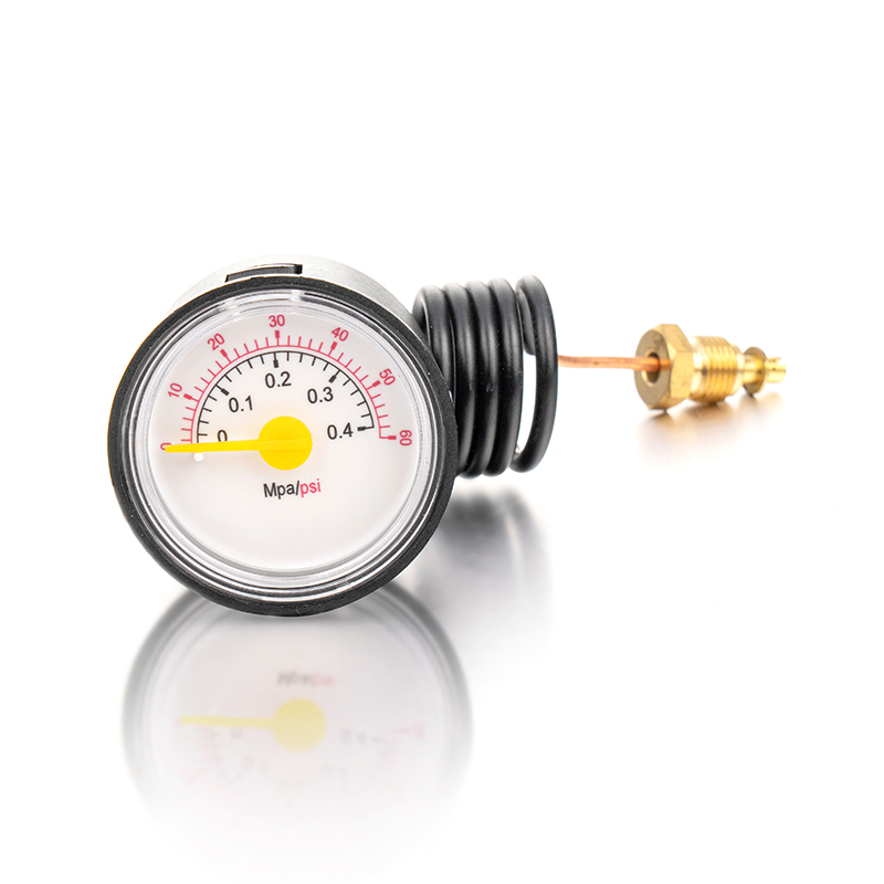
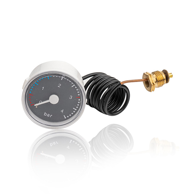
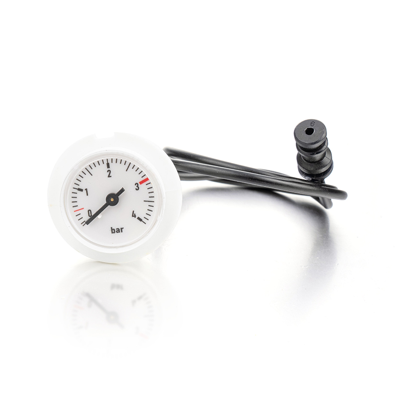
The dual-readout instrument is produced in several configurations so that it can be matched to the mounting position, the available panel space and the distance between the dial and the sensing point. The most common options are a direct-mount bottom connection, a back connection for mounting on a flat panel, and a capillary version where the temperature bulb is separated from the case. In the square-dial version, the case is designed for flush mounting in a control panel.
Compact bottom connection with both sensing elements inside the case. Best for equipment where the dial can be threaded directly into a service valve or a welded tee on the suction or liquid line.
Pressure connection remains at the instrument, while the temperature bulb is connected by a capillary tube. This allows the dial to be mounted away from a hot or vibrating pipe while the bulb still measures the true line temperature.
Flush-mount square case for control panels. The separate bulb and capillary make it suitable for installations where the display must be at eye level and the process line runs behind the panel.
A bimetallic thermometer without the pressure mechanism, used when the circuit already has a dedicated pressure gauge and only line temperature needs to be monitored.
 HVAC Pressure Thermometer with Dual Dial for Simultaneous ReadingThis combined gauge displays both pressure and temperature, ideal for monitoring refrigerant lines when only temperature is needed alongside an existing pressure gauge. Available in multiple sizes and capillary options.View Product →
From a purchasing point of view, the most important decision is whether the dial will be read from directly in front of the connection or from a distance. If the gauge is installed on the outside of a heat pump casing and the technician stands directly in front of it, a direct-mount bottom connection is the simplest and least expensive option. If the dial must be placed in an electrical enclosure or a control panel while the sensing point is on the refrigerant line, a capillary version avoids the problem of running a long pipe to the panel.
The mounting position depends on what you want to monitor. There is no single location that provides every reading on a circuit, so most systems are fitted with more than one combined instrument. The four most common positions are the suction line, the liquid line, the discharge line and the water or brine side of a chiller or heat pump.
Mounted between the evaporator outlet and the compressor suction service valve. The pressure reading gives the evaporating pressure and the temperature reading gives the true gas temperature, which allows direct superheat calculation.
Installed after the receiver or the condenser outlet, before the expansion valve. The high-side pressure and liquid temperature together give the subcooling figure and indicate whether the condenser is performing correctly.
Placed after the compressor discharge valve. The high pressure and discharge temperature help detect overheating, poor cooling or a failing compressor valve.
On chillers and heat pumps, a combined gauge can also be fitted to the hydronic side to show water pressure and water temperature at the same point, which helps detect low flow or fouled heat exchangers.
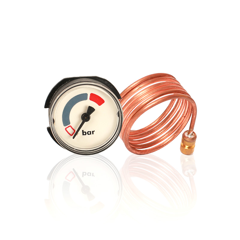 Y28 Series Capillary Pressure Gauges for Remote HVAC MonitoringThese gauges with flexible capillaries allow pressure readings from a distance, suitable for chillers and heat pumps where the sensing point is separate from the display. Built for stability and long service.View Product →
Whichever position is chosen, install the instrument on a straight section of pipe where the flow is stable, not immediately downstream of a bend, a valve or a strainer. Avoid mounting points where oil can collect. On the suction line, a downward connection is preferred so that oil does not rest against the sensing element. On the liquid line, the gauge should be installed before any filter drier that might create a pressure drop between the sensing point and the expansion valve. When a capillary version is used, the bulb must be clamped or strapped tightly to the pipe and insulated where necessary so that it measures the refrigerant temperature rather than the ambient air temperature.
An HVAC pressure thermometer is a small component, but selecting the wrong one can cause a machine to be charged incorrectly or force the technician to adapt the mounting with extra fittings. The following checklist covers the points that should be confirmed before an order is placed.
The most frequent mistake is buying a gauge with an R22 scale and using it on an R410A machine. The second mistake is choosing a bottom connection when the available space is behind a panel and a back connection is needed. The third is ignoring the capillary length and then trying to bend a short tube around a sharp edge, which eventually causes a stress crack at the connection. Reading the data sheet before ordering avoids all three. If your application only needs the pressure side and you prefer a simpler dial, the dual-scale HVAC pressure gauge in the same product family is a practical alternative.
Inside a working refrigeration circuit, the instrument is exposed to refrigerant, compressor oil and sometimes traces of moisture or acid that develop during operation. Over several years, these media can attack brass, copper and ordinary seals. The standard material package for an HVAC pressure thermometer is a brass socket, a copper alloy Bourdon tube and a copper temperature bulb, which is suitable for R22, R134a and most mineral and ester oils. For high-pressure refrigerants such as R410A and R32, or for sites where the environment is corrosive, the wetted parts are available in stainless steel.
 Wholesale HVAC Temperature Gauge with Durable ConstructionEngineered for precise temperature control in HVAC systems, this thermometer offers accuracy and reliability. Material choices accommodate various refrigerants, ensuring compatibility and long-term performance.View Product →
| Component | Standard Material | Alternative | Notes |
|---|---|---|---|
| Socket and Bourdon tube | Brass | 316 stainless steel | Stainless steel recommended for R410A, R32 and high-pressure applications |
| Temperature bulb | Copper or brass | Stainless steel | Use stainless steel for water or brine circuits with aggressive treatment chemicals |
| Capillary tube | Annealed copper | Copper alloy or stainless steel | Annealed copper is easily routed; stainless steel offers better vibration resistance |
| Seals | NBR (Nitrile) | FKM or PTFE | FKM and PTFE resist a wider range of refrigerants and high discharge temperatures |
| Case | Painted steel | Stainless steel case | Stainless steel case recommended for outdoor units near coastlines or chemical plants |
Sealing material deserves as much attention as the metal parts. NBR rubber works well with common refrigerants and mineral oils, but if the system uses a refrigerant with high solubility or operates at high discharge temperatures, FKM seals maintain their elasticity for longer. In systems where moisture is a known risk, the seals and the internal construction should be compatible with desiccant driers and acid-removal filters already fitted in the circuit. The instrument itself cannot prevent system contamination, but choosing the right materials prevents the gauge from accelerating it through internal corrosion.
Mechanical gauges do not usually fail suddenly. They gradually drift because of repeated cycling of the Bourdon tube, wear in the gear mechanism and slow creep in the bimetallic element. The pointer still moves, but its position no longer corresponds exactly to the true pressure or temperature. This gradual error is more dangerous than a sudden failure because the reading still looks credible. The first sign is usually a pressure pointer that does not return exactly to zero when the system is switched off and the line is open to atmospheric pressure.
Recalibration should therefore be a scheduled activity, not a repair task. At the start of each cooling season, or after any repair that opened the refrigerant circuit, check the zero point by isolating the instrument and venting the pressure connection. If the pointer sits on the zero mark, the pressure mechanism is probably still within tolerance. A full calibration with a deadweight tester is recommended once a year for instruments used in service work, and more frequently for gauges that are constantly subjected to pressure fluctuations.
For the temperature side, the verification procedure compares the thermometer reading with a calibrated reference sensor at two or three points across the range. The bulb can be placed in an ice-water mixture for the low point and in warm water for the high point, or compared directly with a laboratory thermometer clamped to the same pipe. If the instrument has removable links inside the movement, a skilled technician can adjust it back to tolerance. In less expensive gauges, replacement is more economical than recalibration.
Overload protection is a separate issue. If the system is protected by a pressure relief valve, the gauge should still be selected so that the maximum pressure reached during normal operation is within the continuous range of the instrument. A gauge is not a safety device and should not be relied on to stop a system from overpressure. The pressure relief functionality of the equipment is handled by the valve, while the gauge simply reports the pressure. Selecting a gauge with a higher range than necessary reduces accuracy, so the correct balance is to stay below 75 percent of the scale under normal conditions.
When an HVAC pressure thermometer produces readings that do not match the behavior of the system, the fault can be in the instrument or in the circuit itself. The quickest way to decide is to check both pointers together. If the pressure pointer is reasonable but the temperature pointer is slow or stuck, the fault is more likely inside the thermometer. If both readings change together but the system performance is poor, the problem is probably the system, not the gauge.
| Observed Symptom | Likely Cause | Corrective Action |
|---|---|---|
| Pressure pointer does not return to zero | Worn gear mechanism or permanent deformation of the Bourdon tube | Recalibrate or replace the instrument |
| Temperature pointer responds very slowly | Damaged bimetallic coil or a crimped capillary tube | Inspect the capillary path; replace the temperature element |
| Both pointers read low on a running system | Refrigerant undercharge or a suction-side leak | Perform a leak check rather than adjusting the gauge |
| Pointer jumps erratically on a vibrating unit | Gear wear or the absence of a liquid fill | Use a liquid-filled case to damp vibration |
| Condensation appears inside the glass | Failed case seal or blocked pressure relief vent | Dry the case, replace the seal and verify the IP rating suits the site |
| Temperature reads high even when the line is cold | External heat affecting the bulb or capillary | Move the bulb away from the compressor discharge or insulate it from radiation |
Environmental factors play a large part in these faults. A gauge mounted in direct sunlight will show an elevated temperature because the case absorbs heat; this is normal and is one reason why the temperature sensing point is often placed in a capillary bulb away from the case. In cold climates, freezing condensation inside the case can restrict the movement until the instrument warms up. In coastal sites, salt air attacks unpainted parts and gradually reduces the readability of the dial. Checking the protection rating and the material of the case before installation reduces the number of unexpected instrument faults during the warranty period.
A pressure thermometer is a precision mechanism despite its rugged appearance. Most premature failures are caused by handling during installation rather than by the measurement itself. The capillary tube is the most vulnerable part: it should be wound in a gentle arc, never bent sharply at the connection, and never used as a handle to carry the gauge. The case should be tightened only by the hexagonal socket or the fixing nut, never by rotating the body of the case.
When a gauge is removed from a system for maintenance, replace the protective cap immediately. The socket opening is easily blocked by paint, dust or thread tape, and a blocked socket produces a pressure reading that lags behind the actual system condition. It is also good practice to keep a simple record of which instrument is installed on which machine, along with the date of the last calibration check. That record makes it easy to spot a gauge that is drifting gradually before it causes a false service diagnosis.
No. The pressure scale is fixed at the factory, and R410A operates at a considerably higher pressure than R22. If an R22 gauge is used on an R410A circuit, the pointer will exceed the scale on a hot day and the Bourdon tube can be permanently damaged. An R410A gauge has a 0 to 4.2 MPa scale, while an R22 service gauge typically has a 0 to 2.5 MPa scale. Always specify the refrigerant when ordering.
The temperature is shown either by a secondary pointer on an inner scale or by a separate small dial inside the main dial face. The main pointer always indicates pressure, and the secondary pointer indicates temperature. In a capillary version, the temperature sensing bulb is mounted at the pipe and the capillary transmits the movement back to the case, allowing the dial to be located in a panel.
No. The standard configuration measures the temperature directly at the sensing element. The bulb is clamped against the outside of the pipe or inserted into a small brass pocket that is threaded into the line. A separate clamp probe is only required if the gauge is mounted so far from the pipe that the capillary cannot reach, in which case a longer capillary should be ordered.
Choose a capillary version when the dial must be mounted on a control panel or an electrical enclosure away from the refrigerant line, or when the pipe temperature is high enough to damage the case over time. The capillary length required is the distance from the mounting point to the sensing point plus extra slack for routing. A direct-mount model is preferable when the gauge can be threaded directly into a service valve or a tee on the line.
The safe working pressure should stay at or below 75 percent of the full-scale value. For example, a 0 to 2.5 MPa gauge should not be used continuously above about 1.9 MPa. Transient pressure peaks during startup or defrost may briefly exceed the continuous limit, but the instrument should not be selected so that normal running pressure sits close to the end of the scale.
The pressure pointer should be checked against zero at the start of each cooling season and after any repair that opened the circuit. A full verification with a deadweight tester and a reference thermometer is recommended once a year for instruments used in regular service work. If a gauge has been subjected to an overpressure event, a severe impact or a refrigerant leak inside the case, it should be checked immediately rather than waiting for the next scheduled inspection.

+86-15105800222
+86-15105800333


Shuangtang Industrial Zone,Liuheng Town , Putuo District, Zhoushan City,Zhejiang Province,China
We will reply to you within 12 hours after receiving the inquiry on working days. Or, give us a call.
The information provided on this website is intended for use only in countries and jurisdictions outside of the People's Republic of China.
Copyright © Zhoushan Jiaerling Meter Co., Ltd. All Rights Reserved.
 Wholesale Pressure Gauge Factory
