 English
 中文简体

Call us
+86-15105800222
+86-15105800333


In a refinery, an ethylene cracker, a gas processing train or a crude tank farm, the Petrochemical Pressure Gauge is the instrument operators trust when a screen freezes, a signal cable fails or a control loop starts to wander. It needs no power, it shows the process state at a glance, and it keeps working through vibration, heat, pulsation and aggressive media. Choosing the right model, however, takes more than matching a thread size and a pressure range. Measuring principle, accuracy class, case construction, wetted materials and hazardous-area rules all influence whether a gauge lasts three months or ten years.
This guide answers three questions that engineers search for most often: what are three types of pressure gauges, what is the most accurate pressure gauge, and what types of gauges are used in oil and gas. It then moves on to the practical side of the Petrochemical Pressure Gauge, covering product families, material choices, calibration, installation and troubleshooting, with reference tables and charts you can use on the plant floor.
The three most common are the elastic-element gauge (Bourdon tube, diaphragm or capsule), the liquid-column manometer, and the electronic digital gauge or pressure transmitter. Each converts pressure into a readable signal in a completely different way.
For calibration work the deadweight tester is the reference standard, with uncertainty down to 0.008 to 0.015 percent of reading. Among everyday instruments, a temperature-compensated digital gauge reaches 0.05 percent of span or better.
Liquid-filled Bourdon gauges, diaphragm seal gauges, all-stainless-steel gauges, safety pattern high-pressure gauges, differential gauges and explosion-proof transmitters cover almost every upstream, midstream and downstream duty.
Pressure gauges are grouped by the physical effect they exploit. The three families below account for nearly every instrument found in a process plant, and a well-designed Petrochemical Pressure Gauge program usually uses all three at different points of the same unit.
A curved, sealed tube flexes as internal pressure rises. A gear sector and pinion movement amplifies the tiny tip travel into a pointer rotation of about 270 degrees. Diaphragm and capsule elements follow the same logic for low-pressure ranges and viscous media.
Strengths: no power supply, wide range, rugged, easy to read. Limits: sensitive to shock when dry, and reading depends on movement wear and ambient temperature.
Pressure is balanced against the weight of a liquid column. U-tube, well-type and inclined-tube layouts are common. Because the physics is direct, a manometer needs almost no calibration chain.
Strengths: excellent resolution at very low pressure and differential readings. Limits: fragile, bulky, restricted to about 100 kPa and below, and unsuitable for vibrating plant structures.
A piezoresistive, capacitive or thin-film sensor produces an electrical signal that is linearised and displayed digitally. Transmitter versions send 4 to 20 mA, HART or fieldbus signals to the control room.
Strengths: high accuracy, min and max memory, alarm outputs, remote transmission. Limits: needs power, and electronics must be rated for the hazardous zone.
| Parameter | Elastic-Element Gauge | Liquid-Column Manometer | Electronic Digital Gauge |
|---|---|---|---|
| Typical accuracy | Class 0.25 to 2.5 (percent of span) | 0.1 to 0.5 percent of reading | 0.05 to 0.5 percent of span |
| Practical range | -1 bar to 1600 bar | Roughly +/-100 kPa | 10 kPa to 700 MPa depending on sensor |
| Power needed | None | None | Battery or loop power |
| Vibration tolerance | High with liquid filling | Very low | High |
| Remote signal | Optional switch or transmitter add-on | Not available | Built in |
| Best location | Local indication on lines and vessels | Laboratory and low-pressure verification | Custody points, test benches, monitored loops |
Inside the Bourdon element, the oval cross-section tries to become circular when pressure enters, and this pushes the free end outward along an arc. The movement multiplies that motion through a toothed sector, a pinion and a hairspring that removes backlash. Three element shapes are used in a Petrochemical Pressure Gauge: the C-shaped tube for general ranges, the helical coil for high pressure and better stability under pulsation, and the spiral tube for low pressure and higher torque.
Element material matters as much as geometry. Copper alloys work for water, air and mild hydrocarbons, but they are excluded where ammonia, acetylene or hydrogen sulfide may be present. For plant duty the element is normally 316L stainless steel, with Monel, Hastelloy C276 or tantalum used where corrosion data demands it.
Accuracy is not a single number. It combines reference uncertainty, linearity, hysteresis, repeatability, temperature effect and long-term drift. The ranking below places common instruments by their typical uncertainty, shown on a logarithmic scale so that very small values remain visible.
A deadweight tester generates pressure by loading calibrated masses onto a precisely ground piston and cylinder of known effective area. Because the result follows from mass, local gravity and area, the pressure is traceable to national standards without relying on an electrical sensor. This is why a deadweight tester sits at the top of the calibration chain in every serious laboratory.
On the plant itself, the most accurate pressure gauge you can install is usually a digital gauge or transmitter with temperature compensation and a stable sensor. The line chart below illustrates why. A mechanical gauge adds roughly 0.4 percent of span of error for every 10 K of departure from the 20 degree Celsius reference temperature, as allowed by common dial gauge standards. A compensated electronic sensor flattens that effect.
Specifying the tightest accuracy class everywhere wastes money and can even reduce reliability, because precision movements are more delicate. The better question is which error the process can tolerate. The factors below decide the answer for a Petrochemical Pressure Gauge.
Both ambient and process temperature move the zero point. Fit a siphon or pigtail on hot lines, and choose a temperature-compensated sensor where the reading drives a calculation.
Electronic sensors drift slowly, often 0.05 to 0.2 percent of span per year. Mechanical movements drift through wear and set of the elastic element after overpressure.
A start-up surge or water hammer can exceed the normal span several times over. A pressure limiting device or a higher overload rating protects the element.
Pulsation, corrosion, sand or crystallising media decide how fast accuracy erodes. A stable class 1.0 gauge with a seal beats a fragile class 0.25 gauge that is clogged within a month.
| Accuracy Class | Permissible Error (percent of span) | Typical Dial Size | Typical Use |
|---|---|---|---|
| 0.25 | +/-0.25 | 160 mm and 250 mm | Laboratory comparison and test benches |
| 0.6 | +/-0.6 | 100 mm and 160 mm | Process control points |
| 1.0 | +/-1.0 | 100 mm and 160 mm | General process indication |
| 1.6 | +/-1.6 | 63 mm to 100 mm | Utility lines and skids |
| 2.5 | +/-2.5 | 40 mm to 63 mm | Non-critical trend indication |
Oil and gas facilities span three very different environments. Wellheads and gathering lines face high pressure and sand, pipelines face long unattended operation, and refineries face heat, corrosion and constant vibration. The gauge families below are matched to those realities.
Wellhead, choke manifold, injection skids and test separators demand high-pressure safety pattern gauges, often with 316 stainless steel wetted parts and glycerin or silicone filling. Sour wells add H2S, so material selection follows ISO 15156 guidance.
Compressor stations, metering skids and pump stations use liquid-filled gauges for pulsation and digital gauges for proving and verification. Remote valve sites favor battery-powered digital gauges that hold min and max values.
Crude units, hydrocrackers and ethylene plants rely on the Petrochemical Pressure Gauge with diaphragm seals, hot-service siphons and alloy wetted parts. Hydrogen service adds ventilated cases and permeation-aware construction.
| Gauge Type | Key Construction Feature | Typical Location | Problem Solved |
|---|---|---|---|
| Liquid-filled Bourdon gauge | Glycerin or silicone fill, damped movement | Compressor discharge, pump outlet | Pointer flutter, bearing wear |
| Diaphragm seal gauge | Flexible metal diaphragm with fill fluid | Crude, residue, acid and slurry lines | Plugging, crystallising, corrosive contact |
| All-stainless-steel gauge | 316L case, ring, element and socket | Offshore decks, coastal plants | External salt corrosion and internal attack |
| Safety pattern gauge | Solid baffle wall and blow-out back | Wellhead, hydrogenation units | Element rupture protection for operators |
| Differential pressure gauge | Two pressure ports, bellows or piston sensing | Filters, strainers, coalescers | Clogging detection and maintenance timing |
| Explosion-proof transmitter | Ex d or Ex ia certified housing | Classified process areas | Remote monitoring in flammable atmospheres |
A purely mechanical dial gauge has no electrical energy and no ignition source of its own, which makes it a natural fit for classified areas. Any electronic Petrochemical Pressure Gauge, however, must carry certification suited to the zone, commonly flameproof Ex db or intrinsically safe Ex ia, with a temperature class chosen against the autoignition temperature of the gas present. Always verify the certificate number, gas group (IIA, IIB or IIC) and ambient limits before installation.
Our factory builds each model from raw bar stock to the final calibrated unit, so dial, thread, fill fluid and material can be adjusted to the service rather than forced into a catalog compromise. The families below cover the duties described above.
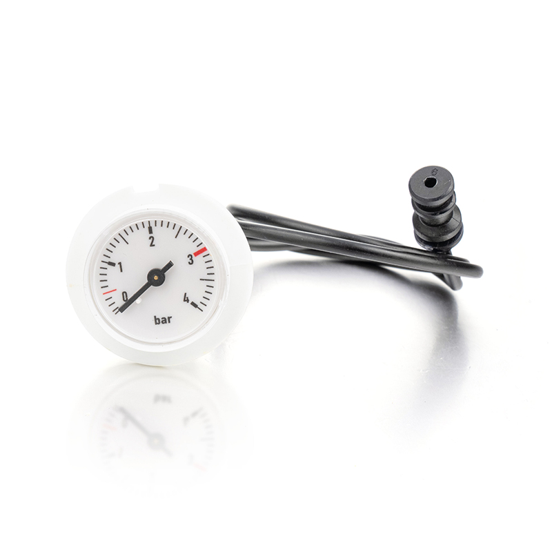
Stainless steel case with a 316L element and bottom connection. Offered in 63, 100 and 150 mm dials, accuracy class 1.0, and an optional liquid-filled case for moderate vibration.
Fully welded case with glycerin or silicone oil filling, designed for reciprocating compressors, dosing pumps and engine skids. The damping removes pointer chatter and protects the movement.
Threaded, flanged or sanitary-style seals with diaphragm materials such as 316L, Hastelloy C276, Monel 400, tantalum or PTFE lining. Suited to viscous crude, bitumen, acids and polymerising media.
Solid front baffle and blow-out back following the safety pattern principle. Chosen for hydrogen, oxygen-cleaned service and wellhead duty where rupture containment is mandatory.
Dual-port design for filters and separators, with optional switch contacts and over-range protection that withstands full line pressure on one side.
Thin-film sensor with temperature compensation, local display, min and max memory, and optional 4 to 20 mA with HART output. Explosion-proof housings are available.
A pressure gauge fails most often because the wrong material meets the wrong fluid. The table lists materials commonly specified for a Petrochemical Pressure Gauge, together with the media that call for them. Treat it as a starting point and confirm against the actual process data sheet.
| Material | Strong Points | Typical Media | Cautions |
|---|---|---|---|
| 316L stainless steel | Balanced corrosion resistance and strength | Hydrocarbons, steam, water, many solvents | Chloride stress cracking at high temperature |
| Monel 400 | Excellent in hydrofluoric acid and seawater | Alkylation units, brine, caustic | Avoid oxidising acids and ammonia-rich media |
| Hastelloy C276 | Broad resistance to oxidising and reducing acids | Wet chlorine, hydrochloric acid, sour gas | Higher cost, longer lead time |
| Tantalum | Near-immune to most acids | Hot sulfuric acid, nitric acid | Attacked by hydrofluoric acid and strong alkalis |
| PTFE lining | Chemical inertness across a wide pH span | Aggressive chemical feeds | Limited vacuum and temperature capability |
| Copper alloy | Economical and stable in neutral media | Air, water, lubricating oil | Never use with ammonia or acetylene |
Economical and effective for ambient temperatures from roughly -20 to +60 degrees Celsius. Good damping for pumps and compressors in moderate climates.
Remains fluid at lower temperatures, so it is chosen for cold regions and offshore winter operation. Viscosity changes slowly with temperature.
Required where the process contacts oxygen or strong oxidisers, because it does not react with them. Used in diaphragm seal systems for such services.
Range selection protects both accuracy and life. A pointer that rests in the lower third of the dial loses resolution, while a pointer that lives near the top of the dial fatigues the element. Under steady pressure, size the span so the normal working pressure falls between one third and two thirds of full scale. Where pulsation is present, keep the maximum working pressure below half of full scale.
For fluctuating loads, limit peak pressure to 50 percent of full scale. For steady loads, the upper working limit is 75 percent of full scale.
| Dial Diameter | Reading Distance | Common Application |
|---|---|---|
| 50 and 63 mm | Up to 1.5 m | Compact skids, instrument panels, sampling systems |
| 100 mm | Up to 3 m | Standard line and vessel indication |
| 150 and 160 mm | Up to 6 m | Pump rooms, compressor halls, elevated platforms |
| 250 mm | Over 8 m | Control reference points and laboratory benches |
Every Petrochemical Pressure Gauge leaves the factory only after it passes a fixed sequence of checks. The sequence below is the path a typical unit follows.
Bar stock and tube material are checked against mill certificates, with positive material identification available for alloy parts.
Tubes are formed on controlled tooling, then welded to the socket by orbital or laser methods for consistent penetration.
The sealed element is held at overpressure, then helium leak tested where the service demands extremely low leakage.
The movement is fitted, linearised and the pointer is set. Hysteresis and friction are inspected before the case is closed.
Each gauge is tested against a reference standard at 0, 25, 50, 75 and 100 percent of span in both rising and falling directions.
Dial print, thread gauge checks and fill level are verified. Units ship with a calibration record and protective packaging.
| Standard | Scope |
|---|---|
| EN 837-1 | Dimensions, metrology, requirements and testing of Bourdon tube gauges |
| EN 837-3 | Diaphragm and capsule gauges |
| ASME B40.100 | Pressure gauges and gauge attachments |
| ISO 15156 | Materials for use in environments containing hydrogen sulfide |
| ATEX and IECEx schemes | Equipment for explosive atmospheres |
| GB/T 1226 | General pressure gauges in the Chinese national system |
A well-chosen instrument can still fail early if it is installed carelessly. The practices below address the most common causes of premature wear and wrong readings.
Take the pressure tapping from the side of a horizontal line, away from elbows, valves and pump outlets where flow is turbulent. For steam and condensable vapor, a downward tapping lets condensate protect the element.
Fit a needle valve or a gauge isolating valve with a bleed port. This allows replacement without a shutdown and allows slow pressure application during start-up.
Where the medium exceeds about 60 degrees Celsius at the gauge, a pigtail siphon traps condensate and keeps the element within its rated temperature.
Use a snubber or restrictor screw to damp rapid cycles from reciprocating machinery. Choose the orifice according to viscosity, since a very fine opening can plug.
Mount the dial vertical and at eye level where possible, with room for a wrench on the socket flats only. Never tighten by turning the case, because this damages the movement.
Oxygen service gauges must be cleaned free of oil and grease and carry a clear marking. Acetylene and ammonia need copper-free construction throughout.
| Symptom | Likely Cause | Corrective Action |
|---|---|---|
| Pointer does not return to zero | Overpressure set or friction in the movement | Replace the gauge and add a pressure limiter |
| Pointer flutters | Pulsation from the pump or compressor | Use a liquid-filled case and fit a snubber |
| Reading higher than expected in summer | Temperature effect on the element | Add a siphon or a compensated digital gauge |
| Fill fluid clouded or leaking | Seal wear or incompatible fill | Replace with a welded case or correct fill type |
| Sluggish response | Blocked tapping or partly plugged snubber | Clean the line or use a diaphragm seal |
| Dial fogging | Moisture entering through the vent | Select a higher IP rating or a filled case |
Because the factory controls each stage of production, a Petrochemical Pressure Gauge can be adapted to match your piping, safety rules and documentation needs. The options below are the most frequently requested.
Custom scale units such as bar, psi, MPa or kgf/cm2, dual scales, colored zones for operating limits, and tag numbers laser engraved on the case.
Special threads, flanged ends in common pressure classes, welded sockets, and capillary-mounted remote seals for hot or difficult locations.
Inductive or magnetic limit switches, 4 to 20 mA transmitter modules, and Ex-certified wiring options for monitoring systems.
Material certificates, calibration records, pressure test reports and dimension drawings prepared with each shipment.
Oxygen cleaning, silicone-free preparation for paint shop use, and sealed packaging for clean-room delivery.
Sample units for fit checks, datasheet review by our engineers, and recommendations when your medium or temperature is unusual.
Yes. A compound gauge carries a scale from vacuum through zero to positive pressure, for example -1 to 5 bar. It suits pump suction and discharge duties where the line passes through both conditions.
The Bourdon element can take a permanent set after exposure to pressure beyond its elastic limit. The pointer then rests slightly above zero, and the gauge should be replaced or recalibrated.
Select a seal when the medium is viscous, polymerising, crystallising, corrosive to the element, or when hygiene requires a flush connection. The seal isolates the gauge, and the fill fluid carries pressure across the diaphragm.
A 100 mm dial is clear up to about 3 meters. For platforms or pipe racks where operators read from further away, a 150 or 160 mm dial is a better choice.
Choose this construction when sudden element rupture could injure personnel, which is typical for high pressure, hydrogen, compressed gas and wellhead services. The blow-out back directs escaping gas away from the operator.
Not always. Electronics offer better accuracy and remote data, while a mechanical gauge needs no power and keeps working during an electrical outage. Many plants install both on critical lines.
Send us the medium, pressure range, temperature, connection standard and hazardous area classification. Our engineers will return a recommended model, material list and drawing for your review.

+86-15105800222
+86-15105800333


Shuangtang Industrial Zone,Liuheng Town , Putuo District, Zhoushan City,Zhejiang Province,China
We will reply to you within 12 hours after receiving the inquiry on working days. Or, give us a call.
The information provided on this website is intended for use only in countries and jurisdictions outside of the People's Republic of China.
Copyright © Zhoushan Jiaerling Meter Co., Ltd. All Rights Reserved.
 Wholesale Pressure Gauge Factory
