 English
 中文简体
中文简体


Call us
+86-15105800222
+86-15105800333


Picture this: a maintenance technician walks up to a compressor skid, glances at the discharge line, and sees the needle pointing at 8. The immediate question is — 8 bar, 8 psi, or 8 on the secondary kPa scale? Far too many operators have made that exact mistake, and the cost shows up quickly as a tripped safety valve, a throttled production line, or a pump running outside its rated window.
The good news is that every analogue pressure gauge follows the same basic logic. If you identify the pressure unit, the value of each scale division, and the position of the needle, you can read any gauge on site — from a small 40 mm gauge on a coffee machine to a 100 mm process gauge on a pipeline. This guide explains the reading process step by step, shows what the markings on the dial actually mean, and covers the practical mistakes that cause misreadings in real working environments.
A pressure gauge is meaningless until you know what each number represents. The most common units in industrial and commercial use are psi, bar, kPa, and MPa. In North America, psi is the default on most air and hydraulic gauges. In Europe, the Middle East, and much of Asia, bar is the standard. kPa appears frequently on HVAC and water treatment gauges, while MPa is reserved for high-pressure hydraulic systems and test equipment.
Many gauges print the unit directly on the dial face. Others carry two scales — for example, an outer ring in psi and an inner ring in bar or kPa. Choosing the wrong scale on a dual-scale gauge creates a serious error: 100 psi is about 6.9 bar, not 100 bar. That kind of misreading is easy to make under time pressure, and it is one of the most frequent mistakes when someone first uses an unfamiliar gauge.
| Unit | Typical application | Equivalent value |
|---|---|---|
| psi | Air compressors, tires, hydraulic tools | 0.069 bar |
| bar | Industrial gauges, pumps, compressors | 100 kPa |
| kPa | HVAC systems, water treatment, low-pressure air | 0.01 bar |
| MPa | High-pressure hydraulics, pressure testing | 10 bar |
| kgf/cm² | Legacy machinery and machine tools | 0.981 bar |
If the gauge has more than one scale, check the printed unit label next to the scale you intend to read. This small habit removes the most common source of incorrect readings. For routine air and water lines with normal working pressure below about 10 bar, a compact gauge with a 60 mm dial is a practical choice — readable at a glance and easy to install on panels or directly on equipment.
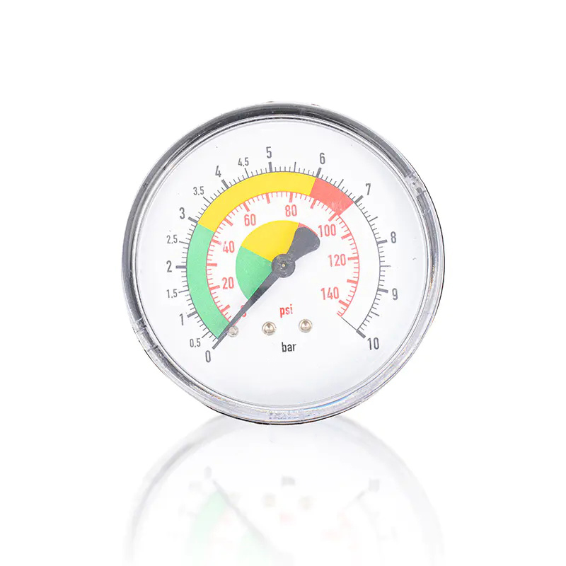 Y60 Series Compact Pressure Gauge for Panel or Equipment InstallationThis 60 mm dial gauge suits routine air and water lines below about 10 bar, offering a readable display and easy installation. Its durable build supports accurate monitoring in mechanical pneumatic systems.View Product →
Once you know the unit, the reading itself is a four-step process. Use the same sequence every time, and you will be able to read any gauge accurately, even one you have never seen before.
The numbers printed around the dial show the maximum pressure the instrument can indicate. A gauge marked 0–16 bar measures up to 16 bar. Do not judge the range from the size of the case — a 100 mm case can hold a 0–1 bar scale or a 0–1000 bar scale, depending on the internal element.
Look at two consecutive major numbers and count the small divisions between them. If the distance between 0 and 1 bar contains 10 divisions, each division equals 0.1 bar. If the distance between 0 and 10 psi contains 10 divisions, each division equals 1 psi. This is the step that is most often skipped, and it is also the step that causes the largest reading errors.
The needle rarely stops exactly on a printed mark, and changing your viewing angle can move the apparent needle position by half a division or more. Face the gauge directly, keep your eye level with the needle, and use the mirror arc on the dial if one is present. The mirror lets you align the needle with its own reflection so that the reading is repeatable.
On a dial with two scales, every physical needle position corresponds to two different numbers. Decide which scale matches the pressure unit used by your equipment, then write the reading together with the unit. Record "4.6 bar", never just "4.6". This single habit prevents a large share of downstream troubleshooting errors.
Follow the same checklist on every gauge:
Why would a manufacturer print two scales on one dial? Because the same physical pressure can be expressed in different units, and equipment built for different markets may require one unit or the other. A common example is a tire gauge that shows 35 on the inner scale and 240 on the outer scale. These are the same pressure: 35 psi equals approximately 240 kPa.
The numbers are not in conflict, and neither scale is more accurate. The rule is to match the reading to the unit used in your system documentation. If the manual says "inflate to 35 psi", read the psi scale. If the system is metric and uses bar or kPa, read the corresponding scale. Ignoring the unit and simply noting the bigger number creates errors that can range from a nuisance on a filling line to a serious safety issue on a pressurized vessel.
Used on equipment designed to North American standards. Common in tire service, hydraulic tools, and older compressor systems. The range is usually 0–300 psi or higher.
Used on metric-designed equipment. Common in European, Middle Eastern, and Asian markets for process lines, HVAC, and water systems. The same needle position shows a smaller number in bar and a much larger number in kPa.
When a gauge combines psi and kPa, the ratio is roughly 1 psi = 6.9 kPa. When it combines psi and bar, the ratio is roughly 1 psi = 0.069 bar. A quick look at the printed scale label is all it takes to avoid mixing them up, and this is exactly where dual-scale HVAC pressure gauges earn their reputation as a practical solution in systems with mixed-market components.
The reading logic — unit, range, division, needle — is the same for every mechanical gauge, but the mechanism inside the case changes the usable pressure range and the sensitivity of the pointer. Knowing the type behind the dial helps you interpret what the needle tells you and warns you when a gauge is out of its comfort zone.
The most common industrial gauge. A curved tube straightens as pressure rises and moves a pointer through a gear mechanism. Covers ranges from about 0.1 bar up to several thousand bar. Linear scale, dependable, and low cost.
Uses a flexible diaphragm instead of a tube. Better for low to medium pressures and for corrosive or viscous media, because the diaphragm can be protected with a chemical seal or an isolating element.
Built for very low pressures, often expressed in millibar. The measuring element consists of two welded diaphragms forming a capsule. The scale is stretched to make small pressure changes clearly visible.
Displays the value as a number and eliminates parallax error completely. Response time, battery condition, and sensor range are the limiting factors, and the reading is only as good as the calibration state of the electronics.
When the process runs below about 1 bar, a general-purpose gauge tends to show only a small needle movement. A capsule gauge uses a different sensing element that expands the scale, so small pressure differences become clearly visible.
 Capsule Pressure Gauge for Low-Pressure Applications with Expanded ScaleDesigned for processes below about 1 bar, this gauge uses a diaphragm sensing element to make small pressure differences clearly visible. It responds quickly and suits gases and liquids in various industrial settings.View Product →
Reading problems fall into three groups: the needle rests at the wrong place when the system is off, the needle moves constantly while the system is running, or the needle points at the correct value but the person behind it misreads the scale. Here is how to recognize each one and what to do about it.
Check the gauge when the system is fully depressurized. A needle that points above zero will make every future reading high by the same amount. A small offset of less than half a division can be taken into account, but a needle that hangs well above zero or presses against the stop pin usually indicates a damaged spring element or a bent pointer. Replace the gauge rather than live with a wrong reference point.
On reciprocating compressors and piston pumps, the pressure pulses make the needle jump across a wide band. The true average pressure sits in the middle of the band, but estimating it by eye is not accurate. A liquid-filled gauge inside the case dampens these pulses and holds the needle steady, which gives you a readable average without guesswork.
Needle behaviour on a pulsating discharge line: undamped gauge vs liquid-filled gauge.
Red line: undamped gauge following pressure pulses. Blue line: liquid-filled gauge showing a steady average.
On permanently vibrating machines — pumps, compressors, and engine-driven equipment — a liquid-filled seismic pressure gauge protects the internal mechanism and keeps the needle readable over a long service life.
Seismic Pressure Gauge with Damping Oil for Vibrating MachineryFilled with low-viscosity damping oil, this gauge withstands vibration and shock on pumps, compressors, and marine equipment. Its luminous dial aids reading in dark conditions, ensuring reliable pressure monitoring.View Product →
Because the needle sits above the dial face, your eye movement changes the apparent angle of the needle. Mirrored scales solve this by letting you align the needle and its reflection. Without a mirror, stand directly in front of the gauge and keep your eye at the same height as the needle. On a small dial with fine divisions, correct viewing angle can reduce the reading uncertainty by half a division.
Dial markings vary from manufacturer to manufacturer, but the method of breaking them down never changes. The table below walks through four typical gauge ranges and shows exactly how to convert the needle position into a correct reading.
| Gauge range | Value between major marks | Divisions between majors | Value per division | Example needle position | Correct reading |
|---|---|---|---|---|---|
| 0–1 bar | 0.1 bar | 10 | 0.01 bar | Third small mark after 0.3 | 0.33 bar |
| 0–16 bar | 1 bar | 10 | 0.1 bar | Sixth small mark after 4 | 4.6 bar |
| 0–100 psi | 10 psi | 10 | 1 psi | Third small mark after 70 | 73 psi |
| 0–25 MPa | 5 MPa | 10 | 0.5 MPa | Halfway between 10 and 15 | 12.5 MPa |
Notice that the calculation is the same in every row: find the major mark below the needle, add the number of small divisions times the value per division, and keep the unit attached to the result.
Look for the unit printed on the dial face, usually directly above or below the scale arc. If the dial has two scales, each scale has its own unit label. Match the number with the matching unit before you record the reading. When no unit is printed, the gauge is likely a custom-manufactured item; check the technical drawing of the equipment instead of guessing.
It defines the maximum error allowed, expressed as a percentage of the full scale. A 0–16 bar gauge with class 2.5 can deviate by up to 0.4 bar at any point on the scale. If the needle reads 8 bar, the actual process pressure is between 7.6 and 8.4 bar, assuming the gauge is correctly calibrated. For tighter tolerance, choose class 1.6 or 1.0.
The most common causes are a pointer installed with an offset, a mechanical shock that deformed the sensing element, or wear in the movement. A small offset under half a division can be tolerated in non-critical service, but a large offset should be corrected by recalibration or gauge replacement.
Yes, when the needle is stable. In pulsating systems, the average position in the middle of the oscillation band is the best estimate, but it is not a precise reading. Install a liquid-filled gauge or a snubber to smooth the pulses if stable high-accuracy readings are required over time.
There is no universal interval because the operating environment is the main factor. Instruments in continuous industrial service are usually checked once a year, while gauges in safety-related or harsh duty may be verified every six months. The best practice is to compare the gauge against a reference standard whenever the system is shut down for maintenance.
A correctly read gauge still delivers a wrong value if the instrument has drifted out of specification. Mechanical gauges are simple devices, but they depend on three conditions: protection from over-range, protection from vibration and corrosion, and regular calibration against a known reference.
Over-range is the quickest way to destroy a gauge. One severe pressure spike can stretch the Bourdon tube and permanently move the zero point. A practical selection rule is to choose a range so that normal working pressure sits in the middle third of the dial, and to match the internal design to the medium and the environment. If you are evaluating which specification fits your equipment, the practical details in our guide on choosing and using a pressure gauge for accurate readings cover the selection criteria in real working terms.
Finally, the human habit decides the outcome every time: identify the unit, count the divisions, read the needle at eye level, and record the value together with its unit. When a gauge is consistently misread, the fault is rarely in the instrument — it is in the missing checklist. Adopt that checklist on every round, and you will catch the same small problems that operators walk past every day before they turn into downtime. For process-specific requirements such as unusual ranges, dual scales, or liquid filling, check the working pressure and medium details with the instrument manufacturer so the gauge can be matched to your actual operating conditions.

+86-15105800222
+86-15105800333


Shuangtang Industrial Zone,Liuheng Town , Putuo District, Zhoushan City,Zhejiang Province,China
We will reply to you within 12 hours after receiving the inquiry on working days. Or, give us a call.
The information provided on this website is intended for use only in countries and jurisdictions outside of the People's Republic of China.
Copyright © Zhoushan Jiaerling Meter Co., Ltd. All Rights Reserved.
 Wholesale Pressure Gauge Factory
