 English
 中文简体

Call us
+86-15105800222
+86-15105800333


Pressure gauge vs pressure transducer is not a contest between old and new technology. It is a selection decision based on where the pressure information must go. A mechanical pressure gauge gives a local, direct reading at the installation point. A pressure transducer converts pressure into an electrical signal for a controller, display, logger, or remote monitoring system. If an operator stands beside the line and needs an immediate visual check, a gauge is often the simplest answer. If a PLC, alarm panel, or data platform must receive pressure continuously, a transducer is usually the correct starting point.
The practical rule is simple: use a gauge when the measurement is read by people at the point of use; use a transducer when the measurement is read, recorded, or acted on by a system. Many plants use both. A gauge provides a local sanity check during maintenance, while a transducer supplies the control signal. The choice becomes clearer when you compare signal type, accuracy expectation, process media, environmental stress, and lifecycle cost rather than purchase price alone.
| Selection factor | Mechanical pressure gauge | Pressure transducer |
|---|---|---|
| Primary output | Dial or pointer indication at the installation point | Electrical signal such as 4-20 mA, 0-10 V, or a digital protocol |
| Best fit | Pump discharge, filters, skids, HVAC service points, medical gas lines | Automation, remote monitoring, alarms, trending, closed-loop control |
| Power requirement | None for indication | Usually requires a power supply or loop power |
| Accuracy expectation | Commonly 1.0%, 1.6%, or 2.5% of span | Often 0.25%, 0.5%, or 1.0% of span, depending on model |
| Main risk | Operator misses a change between readings; no remote record | Incorrect wiring, power loss, signal drift, or poor grounding |
The table should not be read as a ranking. A 1.6% gauge may be entirely adequate for a filter housing where the operator only needs to know whether pressure is normal, high, or low. A 0.5% transducer may be unnecessary on a service line that is checked once per shift. The right choice depends on the consequence of a wrong or missing reading.
A mechanical gauge uses a sensing element, commonly a Bourdon tube, capsule, or diaphragm, that deforms under pressure. That movement is transferred through a linkage to a pointer. The result is visible without power, and the reading is available as long as the gauge is installed and not damaged. This direct mechanical chain is why gauges remain common on pumps, receivers, regulators, and packaged equipment.
A pressure transducer uses a sensing element that produces a small electrical change when pressure is applied. Internal electronics convert that change into a standard output. The signal can travel to a controller, display, or data acquisition unit. The transducer does not usually show a local reading unless it is paired with a display. Its value is in repeatable signal transmission, not in visual indication.
This difference affects installation. A gauge needs a pressure connection and enough clearance for the dial. A transducer needs a pressure connection, electrical wiring, a compatible power source, and signal routing. It may also need shielding, grounding, and protection from moisture or vibration. In a small skid with no control panel, the gauge is often the lower-risk installation. In a plant with an existing control architecture, the transducer may be the cleaner integration.
Pressure enters the element, the element moves, and the pointer shows the result. No power, no output scaling, no signal cable.
Pressure enters the sensor, electronics condition the signal, and the controller interprets the output. Wiring and power become part of the measurement.
A gauge and transducer on the same line provide local indication plus remote data. The two readings can be compared during maintenance.
A pressure transducer is selected only after the receiving system is understood. A 4-20 mA loop is common because it carries the signal over long cable runs and has a defined live zero at 4 mA. A 0-10 V output is often used in shorter runs or where the controller expects a voltage input. Digital outputs may be used for pressure switches or simple alarm points, but they do not provide a continuous pressure value.
Power supply details matter. A two-wire loop-powered transducer receives power from the same pair that carries the signal. A three-wire or four-wire device has separate power and signal conductors. If a buyer specifies a transducer without confirming the controller input type, the result can be a device that fits mechanically but cannot be read by the control system. This is a common procurement error in retrofits where an older panel is being updated.
Mechanical gauges avoid this interface problem entirely. They require no input card, no scaling, and no signal calibration. That simplicity is valuable in isolated locations, temporary installations, and equipment that is rented or moved. For a permanent automated line, the lack of a signal is a limitation, not an advantage. Select the device that matches the information path, not the device that seems more modern.
Accuracy is often the first specification compared, but it is frequently misunderstood. A gauge marked 1.6% is usually expressing an accuracy class against the full span, not a percentage of the current reading. A transducer marked 0.5% may also refer to full-scale error, including nonlinearity, hysteresis, and repeatability under defined conditions. Two devices with similar numbers can behave differently after temperature changes, vibration, and time in service.
Resolution is different from accuracy. A large dial with fine graduations can let an operator see small changes, even if the absolute accuracy is modest. A transducer with high resolution can report fine steps in a control system, but that does not guarantee that those steps are accurate. For trend monitoring, repeatability may matter more than absolute accuracy. For custody transfer or safety interlocks, the required accuracy and calibration evidence must be defined before purchase.
For many industrial points, a 1.0% or 1.6% gauge is sufficient because the decision is binary: normal, high, or low. For closed-loop control, a 0.5% transducer is often a better fit. The important question is not which device is more accurate in a catalog, but which device delivers the accuracy the process actually needs.
Media compatibility decides whether a pressure device survives. Clean air, water, oil, refrigerant, steam, caustic solutions, and food-grade fluids place different demands on wetted parts. A standard brass or stainless steel connection may be acceptable for clean water. A corrosive chemical may require a diaphragm seal, PTFE facing, or a fully stainless steel wetted path. High-viscosity media, slurries, and crystallizing fluids can clog a small pressure port and make a standard gauge or transducer unreliable.
Diaphragm seals are common when the instrument must be isolated from the process fluid. The seal transfers pressure through a fill fluid to the sensing element. This protects the instrument from corrosion, solids, and high temperature, but it adds cost and introduces another selection variable: fill fluid compatibility, temperature limits, and seal mounting. A gauge with a diaphragm seal can be a practical local indicator on a chemical line, while a transducer with the same seal can feed a control system.
 Diaphragm Type Pressure Gauge for Corrosive and Viscous MediaFor process isolation, the diaphragm protects the measuring mechanism from corrosive, viscous, crystallizing, or solidifying media and can use stainless steel or alloy diaphragms.View Product →
For sanitary or medical applications, surface finish, cleanability, and material traceability may matter as much as pressure range. For refrigerant work, the gauge or transducer must be compatible with the refrigerant and lubricant, and the scale should match the expected operating range. A device that is accurate in air may fail quickly in a chemically active line if the wetted materials are not reviewed together with the process conditions.
Range selection is a safety decision. A gauge or transducer should normally operate in the middle portion of its span, not at the extreme end. A common practice is to select a range so that normal operating pressure falls between 25% and 75% of full scale. This leaves room for pressure spikes and makes small changes easier to see. A device selected too close to its maximum will be less tolerant of transient events.
Overpressure and burst pressure are not the same. Overpressure describes a pressure the device can withstand without permanent performance loss, often for a limited time. Burst pressure describes catastrophic failure. Buyers should ask for both when the line can see water hammer, pump start-up surges, or valve closure events. A gauge with a mechanical stop may survive a spike that would damage a thin sensing diaphragm, while a transducer may include electronic protection but still have a mechanical limit.
Do not use a high-range device simply because it is available. A gauge with a 0-100 bar range used on a 5 bar line will compress the useful reading into a small arc. A transducer with the same oversized range may lose resolution in the control system. Select the narrowest range that safely covers normal operation and expected excursions.
Vibration destroys pressure instruments quietly. A dry mechanical gauge on a reciprocating pump can show pointer flutter, wear in the movement, and eventually fail. Liquid-filled gauges are commonly used to damp vibration and pulsation. A snubber, restrictor, or capillary may also be needed. A transducer can be configured with electronic damping, but it still needs a mechanically sound installation. Electronics do not fix a sensor that is being shaken apart.
Pulsation is a separate issue. Rapid pressure cycles can fatigue a Bourdon tube or a diaphragm. A gauge may show a blurred reading, while a transducer may produce a noisy signal that the controller filters or misinterprets. The installation should include a proper isolation valve, a suitable connection, and enough straight length or damping to protect the device. In severe service, a diaphragm seal or remote mounting may be more reliable than a direct-mounted instrument.
The chart is qualitative, not a substitute for vibration data. It shows why installation method matters as much as the device category. A well-selected gauge with a siphon, snubber, or liquid fill can outperform a poorly installed transducer in the same location.
Temperature affects both categories. A mechanical gauge may lose accuracy when the ambient temperature moves far from the calibration condition. A transducer may have compensated electronics, but compensation has limits. Media temperature can be more severe than ambient temperature, especially on steam lines or hot oil. In those cases, a siphon, cooling element, capillary, or diaphragm seal may be required.
Enclosure protection also matters. A gauge installed outdoors needs a case that resists moisture and ultraviolet exposure. A transducer needs an appropriate ingress protection rating for washdown, humidity, or dust. Cable entry is a common weak point. A device rated for the enclosure but installed with an unprotected cable gland can still fail. For hygienic service, the housing should be cleanable and the materials compatible with cleaning chemicals.
Read the temperature specification as a complete condition, not a single number. It should state the ambient range, media range, and compensation range. If the process exceeds those limits, the device may still function but the published accuracy may no longer apply. In critical service, this distinction should be part of the purchase specification.
A mechanical gauge usually has a lower purchase price and simpler installation. A pressure transducer usually costs more because it includes a sensor, electronics, and signal conditioning. The installed cost gap can widen when wiring, power supply, control input, and commissioning labor are included. However, the lower-purchase-price device is not always the lower-cost solution. If the transducer enables remote monitoring, reduces manual rounds, or prevents an unplanned shutdown, the lifecycle value can be much higher.
| Cost factor | Mechanical gauge | Pressure transducer |
|---|---|---|
| Device cost | Generally lower | Generally higher |
| Installation | Pressure connection only | Pressure connection, power, signal wiring, and configuration |
| Routine operation | Requires manual reading and recording | Can feed continuous logs and alarms |
| Maintenance | Visual inspection, occasional calibration or replacement | Signal checks, calibration, wiring inspection, and power checks |
| Hidden value | Immediate local diagnosis during a walkdown | Trend data, remote alarms, and process optimization |
A simple way to decide is to ask what a missed pressure event costs. If the cost is a minor maintenance note, a gauge may be enough. If the cost is a spoiled batch, an overheated pump, a safety incident, or an unplanned shutdown, the transducer and its integration cost may be justified. The answer changes by process, not by product category.
Mechanical gauges remain the better choice when the pressure reading is needed at the point of use and no control signal is required. A pump discharge gauge lets a technician confirm that a pump is running and that the discharge pressure is within range. A filter gauge shows whether the element is loading up. A regulator station gauge gives an immediate check during adjustment. These are local diagnostic tasks, and a dial is often faster than opening a control screen.
Gauges also have an advantage where power is unavailable or undesirable. Remote skids, temporary equipment, rental systems, and field installations may not have a reliable power source. A gauge needs no power supply, no signal cable, and no controller configuration. It is also easy to verify visually during a walkdown. For equipment that is shipped or moved, a gauge can be a simpler service item than a transducer with exposed wiring.
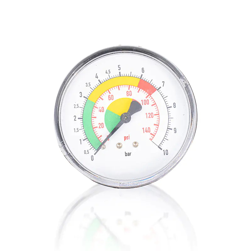 Y60 Mechanical Pressure Gauge for Pneumatic and Industrial SystemsA no-power local indicator for compressed air, nitrogen, oils, and pneumatic lines, with Y60 sizing and multiple pressure ranges for direct field checks.View Product →
HVAC and refrigeration service points often use gauges because the technician works directly at the equipment and needs a fast reading. Water treatment lines use gauges to show pump pressure and filter condition. Medical gas systems use dedicated gauges that are selected for the gas, range, and safety requirement. In these cases, the question is not whether a transducer is more advanced, but whether the added signal path improves the task. Often it does not. For broader selection guidance, see this reference on industrial pressure gauge selection.
A transducer earns its cost when the pressure value must travel beyond the installation point. If a controller needs to start and stop a pump based on pressure, a transducer provides the input. If a data logger needs a continuous record, a transducer provides the signal. If an alarm must notify an operator in another room, the transducer is part of that chain. A gauge can be watched, but it cannot send a signal on its own.
Transducers are also useful when pressure is one variable in a larger calculation. Flow, pump efficiency, compressor loading, and filter loading can be derived or inferred from pressure data. A gauge provides a snapshot; a transducer provides a time series. That time series can reveal a slowly fouling filter, a failing pump, or a valve that is not fully opening. The value is not just the pressure reading, but the pattern of pressure over time.
 HVAC Pressure Transducer Sensor for Real-Time ControlProvides electrical pressure signals for HVAC and refrigeration control, with multiple 0–4 to 16 bar ranges and IP65 protection for continuous monitoring.View Product →
In HVAC and refrigeration systems, transducers support automatic control and remote diagnostics. A refrigerant pressure gauge remains useful for service work, but the control system needs a signal. The same logic applies to compressed air, water treatment, and process skids. When the pressure reading must trigger an action, the transducer is the natural choice. A refrigerant-specific gauge can still complement the system for local service checks, as shown in this refrigerant pressure gauge option.
A hybrid layout uses both devices at the same measurement point or nearby. The transducer feeds the control system, while the gauge gives maintenance staff a local check. This arrangement is common on pump skids, boiler feed systems, and packaged HVAC equipment. The gauge does not replace the transducer signal, and the transducer does not replace the convenience of a dial. Each serves a different user and a different task.
Redundancy has limits. Two devices on the same port can be affected by the same blockage or the same process surge. A gauge and transducer installed on separate taps may provide better diagnostic value than two devices sharing one connection. The comparison between local and remote readings can also reveal signal problems. If the gauge shows normal pressure while the control system shows a fixed high value, the technician has a useful clue about wiring, power, or sensor health.
For critical service, define which device is the primary measurement and which is the check. Do not assume that two readings will always agree. Differences may come from calibration, location, temperature, or dynamic effects. A documented comparison procedure is more valuable than adding instruments without a plan.
A disciplined selection process avoids most pressure gauge vs pressure transducer mistakes. Start with the information path, then move to the process conditions, then confirm the installation and lifecycle details. The checklist below can be used in a specification review or a purchase inquiry.
Buyers should also confirm the pressure connection, dial size, scale units, and mounting style. A gauge with the wrong thread or a transducer with the wrong output can be technically excellent and still unusable. These details are not secondary; they determine whether the device can be installed and read correctly.
One common mistake is selecting a transducer for a simple local indication point because it appears more modern. This adds wiring, power, and configuration without improving the task. Another mistake is using a gauge where the control system needs a signal, then relying on manual rounds to catch pressure changes. Both mistakes come from starting with the device category instead of the information requirement.
A second risk is ignoring process compatibility. A gauge or transducer that is correct for air may fail in a corrosive liquid or a viscous slurry. Diaphragm seals, material upgrades, and proper isolation are not accessories; they are part of the measurement design. A third risk is oversizing the range. A device that is safe but reads near the bottom of its scale can hide important changes and make calibration checks less meaningful.
Finally, do not separate the instrument from its installation. A gauge needs a suitable port, sealing method, and access for reading. A transducer needs power, signal routing, grounding, and protection from moisture. The best device on paper can fail if the installation ignores vibration, temperature, or maintenance access. Risk control starts with a clear specification and ends with a proper installation review.
Only if the local reading is no longer needed and the control system can accept the transducer signal. A transducer does not provide a dial reading unless it is paired with a display. If operators rely on a local visual check, keep a gauge or use a hybrid arrangement.
A transducer is often available with tighter accuracy, but that does not make it automatically better. A gauge with a suitable accuracy class may be sufficient for a local check. Match the accuracy to the process consequence and the calibration plan.
Yes, most transducers require power. A two-wire loop-powered device receives power from the signal loop, while other designs use separate power conductors. Confirm the controller input and power supply before ordering.
Use a liquid-filled gauge where vibration or pulsation causes pointer flutter or movement wear. It is common on pumps, compressors, and mobile equipment. Check that the fill fluid is compatible with the ambient conditions and the expected service temperature.
It can if the wetted materials and seals are selected for the medium. In many cases, a diaphragm seal is used to isolate the transducer from the process fluid. The seal fill fluid and temperature limits must also be reviewed.
Both are used. A gauge is useful for local pump and filter checks. A transducer is useful for remote monitoring, alarm logic, and trend data. Many water treatment systems use a gauge at the service point and a transducer for control.
Selecting the device before defining the information path. Start with who or what needs the pressure reading, then choose the gauge or transducer, then confirm range, media, accuracy, and installation.

+86-15105800222
+86-15105800333


Shuangtang Industrial Zone,Liuheng Town , Putuo District, Zhoushan City,Zhejiang Province,China
We will reply to you within 12 hours after receiving the inquiry on working days. Or, give us a call.
The information provided on this website is intended for use only in countries and jurisdictions outside of the People's Republic of China.
Copyright © Zhoushan Jiaerling Meter Co., Ltd. All Rights Reserved.
 Wholesale Pressure Gauge Factory
