 English
 中文简体
Call us
+86-15105800222
+86-15105800333


A pressure gauge that reads 0.4 bar high at 6 bar, drops to zero slowly, or jumps when a pump starts is not simply “a bad gauge.” The wrong number is usually a repeatable pattern caused by range selection, installation, medium conditions, mechanical wear, or a calibration shift. The useful question is not whether the gauge is inaccurate, but where the error appears and whether it changes with pressure, temperature, flow, or time.
Start with the reading pattern. A gauge that is wrong at zero and wrong by the same amount at full scale has a zero shift. A gauge that is correct at zero but wrong at the top of the scale has a span or mechanical problem. A gauge that is correct at both ends but wrong in the middle has a linearity or linkage issue. A gauge that moves erratically under vibration or pulsation may still be mechanically sound, but the pointer is being driven by conditions the instrument was not selected to handle.
| Reading pattern | Likely cause | First check |
|---|---|---|
| Reads high at zero and high at pressure | Zero shift, overpressure, bent linkage, or trapped pressure | Vent the gauge, isolate the port, and compare with a known reference |
| Reads correctly at zero but low at pressure | Leak, blocked impulse line, viscous medium, or span error | Check joints, valve position, and impulse-line condition |
| Needle trembles or swings | Pump pulsation, vibration, or missing damping | Check snubber, liquid fill, and mounting point |
| Reading drifts with temperature | Temperature effect on the element, seal, or filling fluid | Compare cold and hot conditions and review specified temperature range |
A gauge can also be within its accuracy class and still mislead the reader. If the dial is too small, the scale divisions are too coarse, or the pointer is viewed from an angle, the indicated value may look wrong even when the instrument is performing as designed. Before replacing a gauge, separate instrument error from reading error. That distinction saves time and prevents repeat purchases of the same unsuitable specification.
Zero error is the easiest fault to confirm. With the gauge isolated from pressure and vented to atmosphere, the pointer should rest on the zero mark or the specified zero reference. If it rests above or below zero, do not assume the gauge is finished. A mechanical gauge may have a zero adjustment, but the adjustment should only be made after confirming that the gauge is vented, at a stable temperature, and not holding pressure from a closed valve or a blocked port.
Span error is different. A gauge may sit exactly on zero and still read 0.8 bar low at 10 bar. That pattern points to a worn Bourdon tube, a stretched linkage, a damaged movement, or a gauge that has been exposed to pressure beyond its intended range. Adjusting the zero screw will not correct a span problem, and forcing the pointer to match at one pressure can make the error worse at another.
Mechanical gauges are not perfectly linear across the whole dial. A modest error near the middle of the scale may be normal for the accuracy class, especially on a small dial. The decision should be based on the required accuracy for the process, not on a comparison with a digital reference that has a much tighter tolerance. If the process needs ±1% of span and the installed gauge is a ±2.5% general-purpose instrument, calibration cannot turn it into a precision gauge. The correct action is to change the specification.
The most common purchasing mistake is choosing a gauge that is technically accurate but poorly matched to the working pressure. A 0-16 bar gauge used on a 4 bar line may be within tolerance, but the useful part of the scale is compressed into the first quarter of the dial. The reader sees a coarse pointer position, estimates between divisions, and concludes that the gauge is inaccurate. In practice, the gauge may be repeating the same value within its class, while the dial resolution is too poor for the task.
A better rule is to operate in the middle half of the scale. For a process that normally runs at 6 bar, a 0-10 bar or 0-16 bar gauge is usually more readable than a 0-40 bar gauge. The upper limit should still allow for pressure spikes, pump dead-head conditions, and test pressures. A gauge that is selected too close to the normal operating point may be damaged by a routine surge, while a gauge selected too far above the operating point will hide small changes.
Resolution also depends on dial size, scale spacing, and pointer length. A 40 mm gauge can be suitable for a compact coffee machine or a small tire inflator, but it is a poor choice for a panel where an operator must read 0.1 bar changes. A 60 mm or 100 mm dial provides more space between graduations, which reduces parallax and reading error. For general plant-air, water, and light hydraulic lines, a Y60 case with a clear dual scale is a practical starting point when the working pressure falls in the middle of the range.
If you are comparing ranges, dial sizes, and connection styles, use the site’s range and readability guidance as a checklist before you request a quote. The goal is not to buy the widest range or the largest dial. The goal is to make the normal operating pressure easy to read, while keeping a safe margin for abnormal conditions.
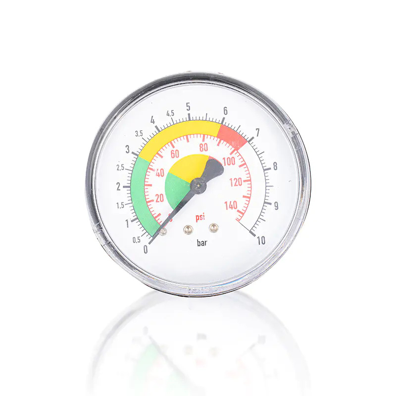 Y60 Series Pressure Gauge for Pneumatic SystemsCompare ranges, dial sizes, and connection options for mechanical pneumatic systems; this gauge supports accurate pressure monitoring in industrial applications.View Product →
A gauge that reads high after maintenance is often not over-pressurized. It may be connected to a trapped volume. If the isolation valve was closed before the pressure was released, or if a vent port is blocked by sealant, the gauge can hold a false pressure for hours. The same thing happens when a needle valve is cracked open too far and then closed quickly, trapping liquid in the impulse line. The pointer looks stable, so the reading is trusted, but the gauge is measuring a closed pocket, not the live process.
Blocked ports are especially common with viscous media, crystallizing solutions, slurries, and water treatment lines carrying sediment. A standard Bourdon tube inlet can become partially plugged, which slows the response and creates a high reading during pump start-up. A diaphragm seal is often the better choice because the measuring element is separated from the medium by a flexible diaphragm and a filled system. The seal does not eliminate maintenance, but it moves the problem away from the small internal passage that is difficult to clean.
High readings can also come from a closed valve on the downstream side of a pump. The pump adds pressure until the relief device opens or the gauge reaches its limit. In that condition, the gauge may be correct and the system may be wrong. Always verify the process path before adjusting the instrument. A gauge that agrees with a known reference while the process is isolated is not necessarily faulty; it may be reporting a real blocked condition.
A low reading is often a leak that is too small to see. Air can enter through a loose compression fitting, a cracked capillary, or a damaged seal, and the gauge responds to a mixture of liquid and gas rather than the liquid alone. The pointer may be steady at low pressure and then become noisy at higher pressure. In a water system, a small air pocket at the gauge inlet can damp the response and make the gauge appear to read low until the pocket is flushed.
Trapped air is particularly misleading on liquid lines. Air is compressible, so the gauge responds slowly and may not reach the true line pressure during a short pump cycle. The same effect can occur after a gauge is replaced if the impulse line is not filled properly. Bleed the line at the gauge connection, then recheck at a stable pressure. If the reading rises as the air is removed, the instrument was probably not the cause.
Viscous media create a different low-reading pattern. The medium may move so slowly into the Bourdon tube that the gauge lags behind the process. During a pump start, the gauge may read low; during a pump stop, it may read high. The pointer is not necessarily damaged, but the response time is unsuitable for the application. A diaphragm seal with a suitable fill fluid, a larger port, or a direct-mounted gauge with a short path can improve response. In extreme cases, the gauge should be selected with a filled case and a suitable damping device rather than a standard dry gauge.
Low readings can also be a span problem. If the gauge reads correctly at zero but low at every higher pressure, the movement or tube may have been damaged by overpressure, or the gauge may have been calibrated with a different reference. Do not correct a span error by turning the zero screw. That will move the whole scale and create a new error at zero. The gauge needs a proper calibration check or replacement.
Temperature changes the gauge, the medium, and the connecting line at the same time. A gauge calibrated at 20°C may read differently at 80°C because the Bourdon tube material expands, the filling fluid changes viscosity, and the seal material changes stiffness. The error may be small, but on a process with tight control limits it can be enough to trigger an unnecessary adjustment. The specified temperature range matters, and so does the temperature of the gauge itself, not only the temperature of the pipe.
On steam service, the siphon is not optional. It creates a water leg that protects the gauge from live steam temperature. If the siphon is missing, too short, or installed horizontally, the gauge may read high during warm-up and then drift as the tube cools. The same principle applies to high-temperature oil and process lines: the gauge should be isolated from the heat source by a suitable standoff, siphon, or capillary, and the specified maximum temperature should be respected.
Temperature can also affect the medium. A liquid that is viscous at room temperature may become thin when hot, which changes the response and the pressure drop in the impulse line. A gas may condense in a cold line and create a liquid slug at the gauge inlet. If the reading changes only when the process heats up or cools down, compare the gauge against a reference at the same temperature before concluding that the instrument is faulty. The installation may be creating the error.
A pointer that trembles is not just difficult to read. Continuous vibration and pressure pulsation wear the movement, loosen the pointer, and eventually change the calibration. The gauge may start with a small error and develop a larger one over weeks. In a pump room, the vibration can come from the pump, the piping, or the mounting bracket. In a reciprocating compressor, the pulsation can be strong enough to damage a dry gauge even when the average pressure is within range.
Liquid fill does not make a gauge immune to vibration. It dampens the pointer movement, but the case, the connection, and the Bourdon tube still receive the mechanical input. If the vibration is severe, a remote-mounted gauge with a capillary or a pressure transmitter may be more reliable than a direct-mounted mechanical gauge. The choice depends on whether the reading is used for local indication, alarm verification, or control feedback.
Check for pointer fatigue by observing the gauge at a steady pressure. A healthy gauge should settle quickly and repeat the same value. A worn gauge may overshoot, stick, or return to a different zero after each pressure cycle. If the pointer can be moved slightly by tapping the case, the movement may be loose or the gear sector may be worn. In that condition, recalibration may not hold. Replacement is usually the more economical decision.
A gauge installed 1.8 m below a pressure tap can read high because the liquid column adds hydrostatic pressure. The error is easy to calculate and easy to forget. Water adds roughly 0.1 bar per meter of elevation, so a 2 m drop can create about 0.2 bar of false pressure. For a low-pressure water system, that is significant. For a high-pressure hydraulic system, it may be negligible. The installation drawing should state the reference point, and the gauge should be calibrated or corrected for the elevation difference when the accuracy requirement is tight.
Orientation matters for more than readability. A gauge mounted upside down may trap air at the connection, and a gauge mounted sideways may collect sediment in the inlet. The dial should be vertical and at eye level where possible. The connection should be at the bottom or side according to the manufacturer’s instruction, and the vent path should remain clear. If the gauge is installed in a pocket or a recessed panel, make sure the case is vented and that the pointer can be seen without parallax.
Capillary lines introduce their own errors. A long capillary adds response lag, and a small bore increases the effect of temperature and viscosity. If the capillary is coiled in a hot area, the filling fluid can expand and create a zero shift. If the capillary is kinked or has a high point, air can be trapped. For HVAC and refrigeration work, the capillary should be routed with a continuous fall or rise as specified, protected from sharp bends, and checked for leaks after installation.
On packaged HVAC equipment, a direct-mounted gauge with a clean, short connection is often easier to service than a remote capillary assembly. The reading should be taken at a stable operating condition, with the system valved to the gauge and the line properly purged. If the gauge is used for commissioning, confirm that the installed range covers both the normal suction and discharge conditions without pinning the pointer.
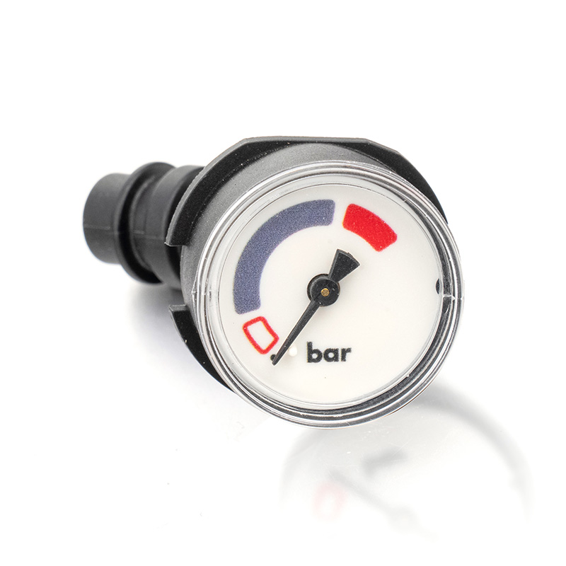 Capillary-Free HVAC Pressure Gauge for Direct MountingSimplifies installation on packaged HVAC equipment with a direct, short connection and reduced capillary maintenance; suited to vibration-prone pressure monitoring.View Product →
A diaphragm seal separates the gauge from the process medium. The pressure is transmitted through a flexible diaphragm and a filled fluid, so the gauge element never sees the corrosive, viscous, or sanitary medium directly. When a sealed gauge reads inaccurately, the problem is often in the seal rather than the gauge. A damaged diaphragm, air in the fill, a wrong fill fluid, or a clamped gasket that blocks the port can all create a repeatable offset or a slow response.
Media compatibility is not only about corrosion. A seal that swells in a solvent can change the internal volume and shift the reading. A diaphragm that becomes stiff in cold weather can slow the response. A filled system with trapped air can read high at zero and low under pressure. If the gauge was accurate before the seal was added, compare the seal assembly with the original specification and check the fill procedure.
For corrosive, viscous, or particle-laden service, a diaphragm-type gauge is often the practical solution because it moves the sensitive element away from the dirty medium and simplifies cleaning. The key is to select the diaphragm, gasket, and fill fluid as a system, not as separate parts. A gauge with the correct pressure range but the wrong seal material will still be unreliable.
 Diaphragm-Type Pressure Gauge for Corrosive and Viscous MediaIsolates the measuring mechanism from aggressive or clogging media, helping maintain reliable readings and simplify cleaning in energy and environmental applications.View Product →
Before sending a gauge out for calibration, perform a simple workshop check to establish whether the error is real. Use a known reference with a tighter accuracy than the gauge under test, apply pressure slowly in increasing steps, and record the indicated value at each point. Then repeat in decreasing steps. The difference between the increasing and decreasing readings is hysteresis. A small hysteresis may be normal; a large one suggests a damaged tube or a sticky movement.
If the gauge is used in a safety function, follow the site’s calibration procedure and use a traceable reference. Do not rely on a quick comparison with a compressed-air line or a pump discharge gauge. Those references may be less accurate than the gauge under test. A proper calibration and maintenance routine includes a defined interval, a written record, and a clear replacement criterion for gauges that cannot be brought back within tolerance.
After calibration, recheck the installation. A gauge that passes on the bench but fails in service usually has an installation problem: trapped pressure, vibration, temperature, or a blocked impulse line. The bench result proves the instrument can be accurate. It does not prove that the installed system presents the correct pressure to the instrument.
The decision should be based on the cost of the error, not only the cost of the gauge. A general-purpose gauge on a utility air line may be replaced without much thought. A gauge on a medical oxygen line, a steam header, or a chemical feed system needs a documented decision. If the error is a simple zero shift and the movement is sound, adjustment may be enough. If the span has moved, the case is corroded, the window is cracked, or the pointer is loose, replacement is usually safer.
| Condition | Practical action | Reason |
|---|---|---|
| Zero shift only, stable span, clean case | Adjust and retest | Low risk if the adjustment holds through a full pressure cycle |
| Span error or large hysteresis | Replace or return to a qualified repair bench | The measuring element or movement is likely worn or damaged |
| Leak at the case or connection | Replace the gauge and inspect the fitting | A leaking case cannot be trusted even if the pointer moves |
| Liquid fill cloudy or low | Replace the gauge or refill only if the design permits | Loss of fill changes damping and may indicate a seal failure |
| Repeated failure at the same installation | Review range, vibration, temperature, and mounting | The installation is causing the failure, not the gauge alone |
Replacement is not a failure of maintenance. It is often the lowest-cost way to restore confidence. The important step is to change the specification if the old gauge repeatedly fails. A new gauge with the same range, the same dry case, and the same mounting point will probably fail in the same way. Add a snubber, change to a liquid-filled case, move the gauge away from heat, or select a diaphragm seal if the medium is the problem.
Incoming inspection prevents a bad gauge from entering the production line and becoming a process problem later. The routine does not need to be complicated, but it should be consistent. Check the basics first, then verify the reading at one or two points that matter for the application. Keep the record with the gauge batch so that a repeat fault can be traced back to the supplier, the specification, or the installation.
Confirm the model, pressure range, connection size, accuracy class, and case material against the purchase specification.
Look for cracks, dents, corrosion, loose bezels, cloudy fill, and signs of leakage at the socket.
Check zero at atmosphere and compare one working pressure against a reference gauge with a tighter tolerance.
Review vibration, temperature, medium compatibility, and available space before releasing the gauge to the line.
For high-volume assembly, a simple fixture with a known pressure source and a pass/fail mark can screen out obvious zero and span errors. For low-volume or critical applications, record the actual reading and the reference used. The extra minute at incoming inspection is usually cheaper than a line stop, a rejected batch, or a field service visit.
Closing a valve can trap liquid in the gauge and impulse line. If the trapped liquid is then heated or compressed, the pointer can stay above the real process pressure. Vent the gauge safely and confirm that the isolation valve is open to the live process before you adjust the instrument.
A gauge can have a correct zero and a wrong span. That pattern often points to a worn Bourdon tube, a damaged movement, or a calibration shift. Check the reading at 50% and 100% of span against a reference. If the error grows with pressure, the gauge needs calibration or replacement.
Yes. A gauge only measures the pressure at its connection point. A blocked port, a closed valve, a trapped air pocket, or a liquid column can present a pressure that differs from the main process. Check the installation and the impulse line before blaming the gauge.
The interval depends on the process, the accuracy requirement, and the history of the gauge. Critical safety, medical, and steam applications usually need a shorter interval than utility air or water lines. A documented routine with a traceable reference is more important than a fixed number that ignores service conditions.
Liquid fill can move inside the case during shipping and temporarily affect the pointer or the zero position. Let the gauge settle upright, check for air bubbles or lost fill, and compare it with a reference. If the fill is cloudy, low, or leaking, the case seal may be damaged.
Not always. A digital gauge may have a higher resolution, but its accuracy depends on the sensor, the electronics, and the calibration. A mechanical gauge with a suitable range and a clean installation can be more than accurate enough for local indication. Choose based on the required accuracy, the environment, and the maintenance plan.
Check for trapped air, a partially closed valve, and a blocked gauge port. Then compare the gauge with a second point on the discharge line. If the gauge responds slowly or jumps when the pump starts, the inlet may be restricted or the gauge may need a diaphragm seal or a different damping arrangement.
Replace the gauge when the span has moved, the pointer is loose, the case is cracked or leaking, the liquid fill is contaminated, or the gauge cannot hold a calibration through a full pressure cycle. If the same installation has failed more than once, change the specification as well as the gauge.

+86-15105800222
+86-15105800333


Shuangtang Industrial Zone,Liuheng Town , Putuo District, Zhoushan City,Zhejiang Province,China
We will reply to you within 12 hours after receiving the inquiry on working days. Or, give us a call.
The information provided on this website is intended for use only in countries and jurisdictions outside of the People's Republic of China.
Copyright © Zhoushan Jiaerling Meter Co., Ltd. All Rights Reserved.
 Wholesale Pressure Gauge Factory
